Current. Too little of it, and you can’t get where you’re going, too much and your hardware’s on fire. In many projects, it’s desirable to know just how much current is being drawn, and even more desirable to limit it to avoid catastrophic destruction. The humble current shunt is an excellent way to do just that.

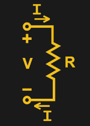
To understand current, it’s important to understand Ohm’s Law, which defines the relationship between current, voltage, and resistance. If we know two out of the three, we can calculate the unknown. This is the underlying principle behind the current shunt. A current flows through a resistor, and the voltage drop across the resistor is measured. If the resistance also is known, the current can be calculated with the equation I=V/R.

This simple fact can be used to great effect. As an example, consider a microcontroller used to control a DC motor with a transistor controlled by a PWM output. A known resistance is placed inline with the motor and, the voltage drop across it measured with the onboard analog-to-digital converter. With a few lines of code, it’s simple for the microcontroller to calculate the current flowing to the motor. Armed with this knowledge, code can be crafted to limit the motor current draw for such purposes as avoiding overheating the motor, or to protect the drive transistors from failure.
In fact, such strategies can be used in a wide variety of applications. In microcontroller projects you can measure as many currents as you have spare ADC channels and time. Whether you’re driving high power LEDs or trying to build protection into a power supply, current shunts are key to doing this.


