 So you’re building a new mechanical keyboard. Or attaching a few buttons to a Raspberry Pi. Or making the biggest MIDI grid controller the world has ever know. Great! The first and most important engineering question is; how do you read all those buttons? A few buttons on a ‘Pi can probably be directly connected, one for one, to GPIO pins. A mechanical keyboard is going to require a few more pins and probably some sort of matrix scanner. But the grid controller is less clear. Maybe external I/O expanders or a even bigger matrix? Does it still need diodes at each button? To help answer these questions the folks at [openmusiclabs] generated a frankly astounding map which shows, given the number of inputs to scan and pins available, which topology makes sense and roughly how much might it cost. And to top it off they link into very readable descriptions of how each might be accomplished. The data may have been gathered in 2011 but none of the fundamentals here have changed.
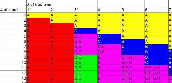
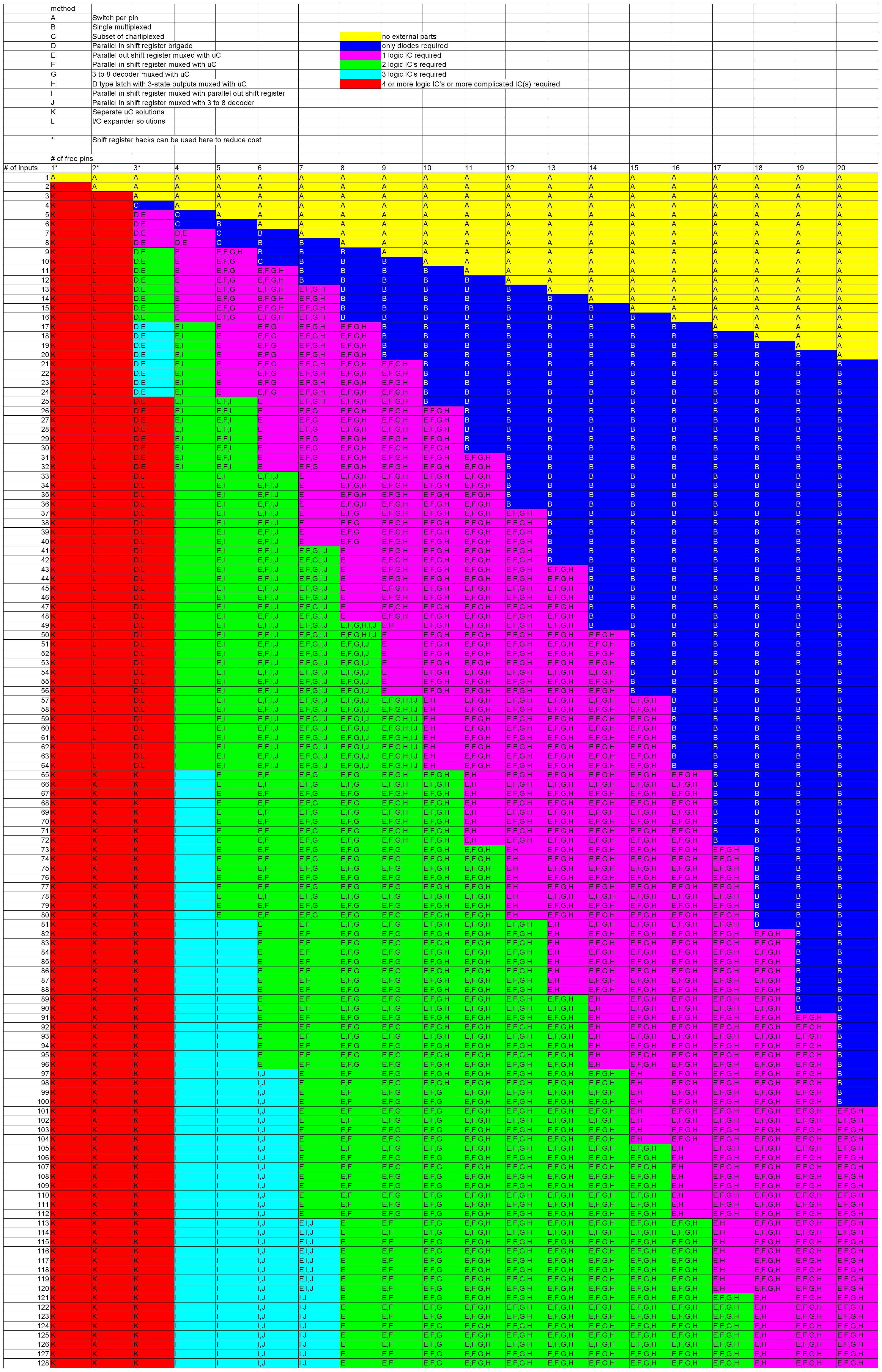
How do you read this chart? The X axis is the number of free pins on your controller and the Y is the number of I/Os to scan. So looking at the yellow band across the top, if you need to scan one input it always makes the most sense to directly use a single pin (pretty intuitive, right?). Scrolling down, if you need to read 110 inputs but the micro only has eight pins free there are a couple choices, keys E and F. Checking the legend at the top E is “Parallel out shift register muxed with uC” and F is “Parallel in shift register muxed with uC“. What do those mean? Checking the table in the original post or following the link takes us to a handy descriptive page. It looks like a “parallel out shift register” refers to using a shift register to drive one side of the scan matrix, and “parallel in shift register” refers to the opposite.
Continue reading “What’s The Cheapest Way To Scan Lots Of Buttons?”


