A 1962 Test Gear Teardown

Although it sounds like some Star Trek McGuffin, a Q-Meter is a piece of test gear that measures the Q factor of a tuned circuit. [Thomas] got a Boonton meter from 1962 that wasn’t in very good shape, but it was a fun teardown, as you can see in the video below. The meter had signs of a prior modification or repair, but still a nice peek into some vintage gear.

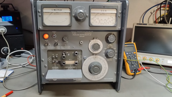
The meter could measure up to 260 MHz (or megacycles in 1962 parlance) and had some unusual features, including an oddly wired AC transformer and a “voltage stabilizer” to ensure a constant AC voltage at the input. We have to admit, we miss the days when our test equipment had gears inside. Then again, we don’t miss the tubes and the high-voltage stuff. Because of the high frequency, the unit even has an oddball acorn tube that you rarely see.

You may notice the meter has a mirror in a strip on the face. This is a common feature of high-precision analog meter movements. The idea is that you move your head until the needle hides its own reflection in the mirror to avoid parallax errors in your reading.

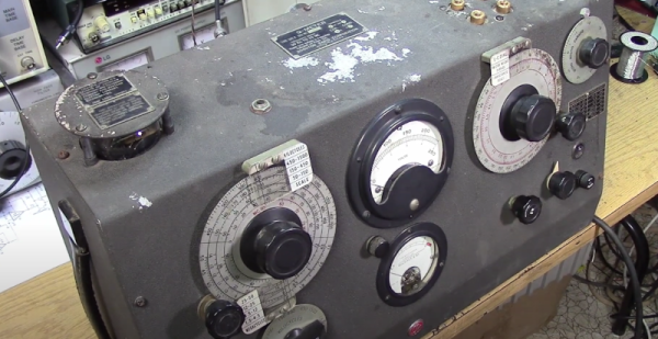
This isn’t the first Q meter we’ve seen; in fact, one was pretty similar but a bit older. While you can get a lot of new gear cheap these days, there’s still something to be said for vintage test equipment.

Continue reading “A 1962 Test Gear Teardown”

Marconi Circuit Magnification Meter Gives Up Secrets

[Thomas] picked up a Marconi TF1245 with dents and dings. We have to admit that we had not heard of a “circuit magnification meter,” but apparently, this was a thing in the late 1960s and early 1970s. Turns out, we have heard of this kind of meter before, but it was called a Q meter. The device works using a very low-impedance resonant circuit and a very high-impedance voltmeter. It measures the ratio of the voltage across the known circuit and the unknown circuit. This particular meter needs an external signal source with very special characteristics. You can see the well-built device in the video below.

The unit didn’t seem to work, but we suspect that it didn’t like his normal signal source. According to a comment in the manual, the matching signal generator delivered 0.5V into a 0.5 ohm load. You could also use a matching transformer to get to the required match.

Continue reading “Marconi Circuit Magnification Meter Gives Up Secrets”

Q Meter Measures… Q, Of Course

If you’ve ever dealt with RF circuits, you probably have run into Q — a dimensionless number that indicates the ratio of reactance to resistance. If you ever wanted to measure Q, you could do worse than pick up a vintage Boonton 160A Q meter. [Mikrowave1] did just that and shows us how it works in the video below.

Most often, the Q is of interest in an inductor. A perfect inductor would have zero resistance and be all reactance. If you could find one of those, it would have an infinite Q because you divide the reactance by the resistance. Of course, those inductors don’t exist. You can also apply Q to any circuit with reactance and the video talks about how to interpret Q for tuned circuits. You can also think of the Q number as the ratio of frequency to bandwidth or the dampening in an oscillator. A versatile measurement, indeed.

It sounds as though you could just measure the resistance of a coil and use that to compute Q. But you really need to know the total loss, and that’s not all due to resistance. A meter like the 160A uses a signal generator and measures the loss through the circuit.

The best part of the video is the teardown, though. This old tube gear is oddly beautiful in a strange sort of way. A real contrast to the miniaturized circuits of today. The Q meter is one of those nearly forgotten pieces of gear, like a grid dip oscillator. If you need to wind your own coils, by the way, you could do worse than see how [JohnAudioTech] does it.

Continue reading “Q Meter Measures… Q, Of Course”