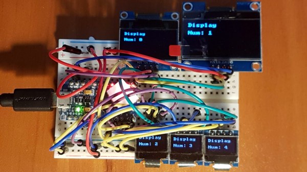
Inexpensive OLED displays with I2C interfaces abound, but there is a catch: they tend to be stuck on I2C address 0x3C. Some have a jumper or solder pads to select an alternate (usually 0x3D), but they lack any other method. Since an I2C bus expects every device to have a unique address, this limits the number of displays per bus to one (or two, at best.) That is all still true, but what [Larry Bank] discovered is a way to get multiple OLED displays working with considerably fewer microcontroller pins than usually needed.
While bit-banging I2C to host one display per bus on the same microcontroller, an idea occurred to him. The I2C start signal requires both clock (SCL) and data (SDA) to be brought low together, but what would happen if the displays shared a single clock line? To be clear, each OLED would — logically speaking — still be on its own I2C bus with its own data line, but they would share a clock signal. Would a shared clock cause attached devices to activate unintentionally?
A quick test consisting of four OLED displays (all with address 0x3C) showed that it was indeed possible to address each display with no interference if they shared a clock. Those four individually controlled displays needed only five I/O lines (four SDA, one shared SCL) instead of eight. The Multi_OLED library is available on GitHub, and in case it is useful for devices other than OLED displays, bit-banged I2C with support for shared clock lines is available separately.
There’s more to do with OLEDs than get clever with signals: check out these slick number-change animations, and that even looks to be a project that could benefit from a few saved GPIO pins, since it uses one small display per digit.


