Octet Of ESP32s Lets You See WiFi Like Never Before

Most of us see the world in a very narrow band of the EM spectrum. Sure, there are people with a genetic quirk that extends the range a bit into the UV, but it’s a ROYGBIV world for most of us. Unless, of course, you have something like this ESP32 antenna array, which gives you an augmented reality view of the WiFi world.

According to [Jeija], “ESPARGOS” consists of an antenna array board and a controller board. The antenna array has eight ESP32-S2FH4 microcontrollers and eight 2.4 GHz WiFi patch antennas spaced a half-wavelength apart in two dimensions. The ESP32s extract channel state information (CSI) from each packet they receive, sending it on to the controller board where another ESP32 streams them over Ethernet while providing the clock and phase reference signals needed to make the phased array work. This gives you all the information you need to calculate where a signal is coming from and how strong it is, which is used to plot a sort of heat map to overlay on a webcam image of the same scene.

The results are pretty cool. Walking through the field of view of the array, [Jeija]’s smartphone shines like a lantern, with very little perceptible lag between the WiFi and the visible light images. He’s also able to demonstrate reflection off metallic surfaces, penetration through the wall from the next room, and even outdoor scenes where the array shows how different surfaces reflect the signal. There’s also a demonstration of using multiple arrays to determine angle and time delay of arrival of a signal to precisely locate a moving WiFi source. It’s a little like a reverse LORAN system, albeit indoors and at a much shorter wavelength.

There’s a lot in this video and the accompanying documentation to unpack. We haven’t even gotten to the really cool stuff like using machine learning to see around corners by measuring reflected WiFi signals. ESPARGOS looks like it could be a really valuable tool across a lot of domains, and a heck of a lot of fun to play with too.

Continue reading “Octet Of ESP32s Lets You See WiFi Like Never Before”

TDOA (Time Difference Of Arrival) Directional Antenna

tdoa-antenna-tutorial

We have posted articles in the past on directional antennas such as Yagi antennas used for transmitter hunting otherwise known as fox hunting. Those types of antennas and reception suffer from one major drawback, which is as you get close to the transmitter the S meter will go full scale. At which time the transmitted signal appears to be coming from all directions. To correct for this problem you need to use clever signal attenuators or change to a poor receiving antenna as well as tuning off frequency effectively making your receiver hard of hearing so that only the direct path to the transmitter is loudest.

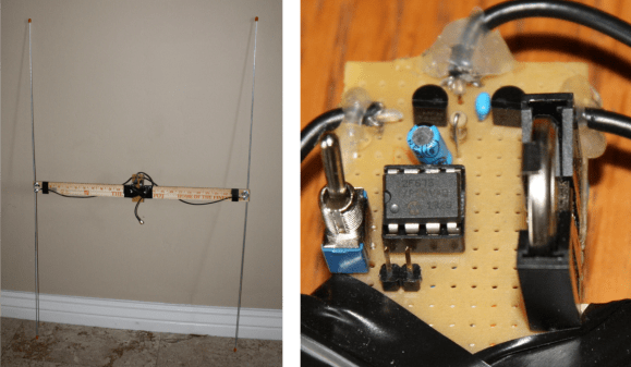
There is another popular type of antenna that you can build yourself called a TDOA which stands for Time Difference of Arrival. [Byon Garrabrant N6BG]  shared a short video tutorial on the functionality of his home built TDOA antenna. Effectively this is an active antenna that uses a 555 chip or, in [Byon’s] case, a PIC chip to quickly shift between two receiving dipole antennas at either end of a shortened yardstick. In his explanation you learn that as the antenna ends move closer or farther from the source a 640 Hz generated audio tone will go from loud to very soft as the antennas become equal distance from the source. This type of directional reception is not affected by signal strength. This means you can be very close to a powerful transmitter and it will still function as a good directional antenna.

The current circuit diagram, BOM and source code are all available on [Byon’s] TDOA page.

The reason [Byon] used a programmable PIC instead of the 555 for his design is because he wants to add a few more modifications such as feeding back the audio output to the PIC in order to programmatically turn on a left or right LED indicating the direction of the transmitter. Furthermore, he plans on adding a third antenna in a triangular configuration to programmatically control a circle of 6 LEDs indicating the exact direction of the signal. When he finishes the final modifications he can drive around with the antenna array on his vehicle and the circle of LEDs inside indicating the exact direction to navigate.

We look forward to seeing the rest of the development which might even become a kit someday. You can watch [Byon’s] TDOA video after the break.

Continue reading “TDOA (Time Difference Of Arrival) Directional Antenna”