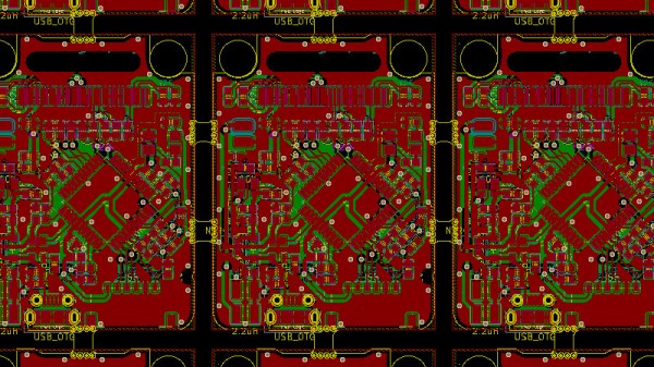
V-Cut Vias Test Your Whole Panel At Once

We might consider PCB panels as simply an intermediate step towards getting your PCBs manufactured on the scale of hundreds. This is due to, typically, an inability to run traces beyond your board – and most panel generators don’t give you the option, either. However, if you go for hand-crafted panels or modify a KiKit-created panel, you can easily add extra elements – for instance, why not add vias in the V-Cut path to preserve electrical connectivity between your boards?

[Adam Gulyas] went out and tried just that, and it’s a wonderfully viable method. He shows us how to calculate the via size to be just right given V-Cut and drilling tolerances, and then demonstrates design of an example board with discrete component LED blinkers you can power off a coin cell. The panel gets sent off to be manufactured and assembled, but don’t break the boards apart just yet — connect power to the two through-hole testpoints on the frame, and watch your panel light up all at once.

It’s a flashy demonstration – even more so once you put light-diffusing spheres on top of the domes. You could always do such a trick with mousebites, but you risk having the tracks tear off the board, and, V-Cuts are no doubt the cleanest way to panelize – no edge cleaning is required after breaking the boards apart. Want to learn about panel design? We’ve written and featured multiple guides for you over the years.

KiCad Panelization Made Easy

There’s a new Python-based script that will panelize your KiCad circuit boards from the command line. The project by [Jan Mrázek] is called KiKit and works on .kicad_pcb files to arrange them in a grid with your choice of mousebites or v-cuts for separating the boards after production.

When working with smaller boards it’s common practice to group them together into panels. This is done to speed up PCB assembly as multiple boards can have solder paste applied, go through a pick and place machine, and be sent into the reflow oven as a single unit. Often this is done manually, but in many cases this script will save you the time while delivering the results you need.

Let’s say you really wanted to make a whole bunch of those Xling open source Tamagotchi-like key fobs we saw a couple of weeks back. Using KiKit you can gang up six of the boards at a time, using “mousebites” to keep them together during production but make it easy to separate them after all the components are soldered:

/usr/local/bin/kikit panelize grid --space 3 --gridsize 2 3 --tabwidth 3 --tabheight 3 --htabs 2 --vtabs 1 --mousebites 0.5 1 0.25 --radius 1 Xling/hardware/xling.kicad_pcb xling_panel.kicad_pcb

You can see that the parameters let you set space between the boards, number of boards in the grid, width of the tabs, tab dimensions, number of tabs between boards, and even the radius of the curve where the tabs meet the board. These settings were pulled from the examples page, which demonstrates outcomes for many different settings options.

If you want to give this a try, we suggest installing directly from the repository, as improvements are ongoing and the pip3 version didn’t have all of the options shown in the examples. For us this was as easy as sudo python3 setup.py install and then calling the script with the full path /usr/local/bin/kikit.

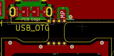
Results from this board are both impressive and cautionary. You can see the top edge of the design is recessed yet the most up-to-date version of KiKit was still able to make the connection. However, how this affects the USB connector on the bottom of the board design may be something to consider before pulling the trigger on your panel order.