A logic analyzer records bus communications between two chips. If you’ve ever had a problem getting two chips to talk, or wanted to reverse engineer a protocol, a logic analyzer is the tool you need to spy on the bus.
The Logic is a USB logic analyzer with eight channels and sampling rates up to 24MHz. Among hobby-level logic analyzers, the Logic has a good mix of features and decent sampling rates. We’ve been following Joe Garrison’s work on the Logic for a long time. If you’ve ever considered bringing a product to market, you can learn a lot from Joe’s blog that documents his development process.
When it debuted, the Logic was so popular that it was hard to buy one. It’s now widely available, and Saleae gave us one to try. Read our review below.
Logic Analyzers vs. Oscilloscopes
Most modern electronics projects will benefit more from a logic analyzer than an oscilloscope. An oscilloscope displays a graph of an analog voltage as it varies over time, such as the curve of a sine wave. A logic analyzer only detects high and low digital states, but it records many signals simultaneously. Logic analyzers dump data to a computer for analysis, very few oscilloscopes have this feature.
What you get

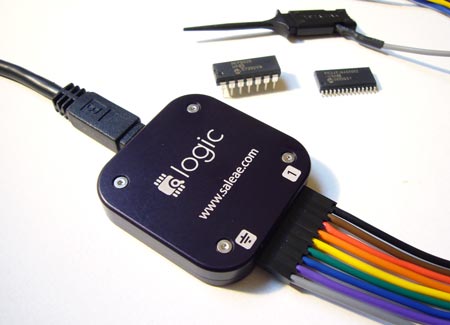
The Logic comes packaged in an external hard drive case. The analyzer is a small, anodized aluminum puck with laser etched signal markers. It’s much smaller than we expected, slightly smaller than a compact flash storage card. A mini-B USB cable is included.
A heavy-gauge cable and nine E-Z-Hooks (5 shown) connect the Logic to a circuit. The hooks are a really nice touch; press the back of the hook to expose a pair of tweezers, grab onto a signal wire, and retract to hold it in place. The retractable tweezers prevent accidental shorts on cramped test circuits.
Software isn’t included, instead you get instructions to download the latest version from the Saleae web site. We always download the latest software, so we appreciate that there’s one less CD headed to the landfill.
Right now, only Windows XP/Vista software is available, but Mac and Linux software should be ready soon. Warning: the Windows version requires .NET 3.5, download the redistributable off-line installer if you don’t want to give internet access to Microsoft’s online installer.
Using it

Using the Logic is simple. Connect the gray ground wire to the ground of the test circuit, then hook into the signal lines you want to record. We connected it to the 32K SPI SRAM that we demonstrated earlier this week. SPI has four important signals; enable, data in, data out, and clock. The E-Z-Hooks make it dead simple to tap into the signals without accidental shorts.
Be mindful of wire orientation. We associate a black wire with ground, but the Logic cable uses gray. Comments on SparkFun’s product page suggest that reversing the connections will damage the Logic.

The software analyzes and displays signal captures. The primary configuration options are the sampling rate (200KHz-24MHz) and number of samples (millions to billions). We were able to sample at 24MHz, but the top speed depends on how much other stuff is using the USB bus. A 24MHz sampling rate can capture signals up to 12MHz, we found this suitable for all the protocols we use. The total number of samples is limited only by the available PC RAM.
There’s a four level trigger that watches the signals, and waits for a specific combination before it starts recording samples. Since we’re analyzing SPI, the most logical place to start capturing is when the SPI enable signal drops at the beginning of a bus transaction. We set the Logic trigger to start sampling when SPI enable is 0 by changing its trigger to ‘0’.

We really like the profiles that decode most common serial protocols; 1-Wire, I2C, SPI, and asynchronous serial. CAN and other protocols will be added eventually.
Profiles suggest names for each signal, and convert squiggly lines into readable byte values. This is a really awesome feature. Without it, you’d have to count clock pulses to identify byte boundaries, and then manually decode the values.
This transaction shows the host issue the read configuration register command (0x05), and the SRAM response (0x41).
![]()
We also tried the 1-Wire decoder with a DS2431 EEPROM. The software identified the 1-Wire reset command, and the 1-Wire ‘search rom’ command (0xf0).
A look inside

The Logic is based on the Cypress Semiconductor CY7C68013A-56PVXC, an Intel 8052 microcontroller with a USB peripheral. The 8052 is an enhanced version of the well-known 8051. We can also identify a 24MHz crystal, which is probably multiplied to 48 or 96MHz by an internal phase-locked loop.
Conclusion
Logic analyzers take the guess work out of debugging inter-chip communication. If you can’t see what’s going on, the best you can do is guess about the problem. When a project won’t work, 99% of the time we can solve the problem immediately by looking at the signals with a logic analyzer. Without it, there’s no easy way to know what’s happening.
The Logic records 8 channels at 24MHz. The Windows software has useful features, and there’s an SDK if you want to write your own apps. Linux and Mac versions are under development. We really like this logic analyzer, and plan to use it to illustrate future articles.
The Logic is $149 at the Saleae website and SparkFun, and Joe is working on EU distribution. If you’re interested in the Logic, but aren’t ready to buy, you can download the software and try it in demo mode.
Hack a Day review disclosure: We asked for a Logic and Saleae sent it to us


I just got my first logic analyzer from a family member for Christmas (as merely a hobbiest, I couldn’t afford dropping money on one for myself… I just don’t have quite enough need) this past year. I wasn’t involved in the decision-making process (thus the disadvantage of *not* buying for oneself), but the got me a USBee SX series — it’s very similar in form factor to this little baby, and I suspect is approximately similar in specifications. Works pretty well to help debug my PIC projects.
http://www.usbee.com/sx.html is the one I got, retails at $139 and has very similar looking software. It can also serve as a signal/pulse generator. The software’s honestly a bit buggy, but in fairness I’m running an older version of it in a Windows 7 VM (VMWare Fusion on a Macbook Pro). My old dev machine (*very* old Windows Server 2k3 laptop which gave up the ghost a couple weeks into January) seemed to support higher sample rates (up to the maximum), but 4 million per second is fast enough for what I need, without a doubt.
In writing this post, I noticed the fact that I’m running an old version… from the looks of it, the newest version has been well tested in Windows 7, and has more features (like easier-to-read decodes of communications protocols), will have to download the latest to see if I get better performance.
But yeah, just an alternative. This looks like the build quality may be a little better, though I don’t see a +voltage output… I use the one on the usbee as a lazy-man’s capture trigger — set the software to watch for a leading edge to trigger a 4 second sample at 4msps, and then just touch a wire to the trigger line and the +5v line — I could just press the mouse, but that’s not always near my circuit.
I recently got one of these at work. boss said it was only $150 what the hell. Everyone loved it so much we are buying about 6 more. Saving a ton of money. software is great and the quality of everything is top notch.
The gray and black wire should definitely be swapped. It would only require a small change in the software to make the color match.
i have one, it’s amazing, love it :)
Any idea on Linux compatibility? Even if only to snaffle raw data.
I haveone of these puppies, its awesome. Pretty blind without it. Very well built.
@mrasmus re: USBee
If you look back through Joe’s blog, you can see that he has a USBee AX. Might or might not explain the similarities.
Personally I get by fine with a cheap ($40-$60) USB scope, la, and function generator. It’s not perfect and it’s not fast, and it’s not intuitive, but it cost less than 1/2 what the cheapest scope in the lab cost and it’s usually more useful. I can imagine a proper la might be even better.
I have one and love it.
I agree with the black and gray wire. It can get confusing.
Even without the decoding, being able to visualize up to 8 signal lines makes debugging and reverse engineering much easier than with my dual channel oscope.
i2c, spi, serial decoding seal the deal.
I picked up one of the old usbee devices from a friend at a discount but I would have paid the full price otherwise. well worth the money.
wow $150 for logic analyzer.
there is more then enough higher bandwidth units with 1/3 of this price, and a lot DIY microchip based logic analyzers
diy one http://www.ikalogic.com/scanalogic_home.php
http://www.pctestinstruments.com/
Much better
I think it’s steal for $150. And when starting out, who wants to build their own test equipment? You have enough to learn!
bluewonder: yea, if you have 389$ laying around. It’s more than twice the cost of this.
therian-
I’m all for diy but the one you posted has some limitations:
“NOTE: The software is actually in beta testing, more functions are coming in next versions like:
– SPI, I2C, UART Decoding
– Saving Screen-shot to JPG file
– Post triggering data sampling.”
Call me when it has Mac support.
Mac support?
Why sacrifice your craft because of a simple operating system?
tom:
boy that was really hard to go here
http://www.saleae.com/logic/
and read
Coming soon to Logic. Cross-platform goodness.
The new software will work with all existing Logics, be free of charge, and include an SDK. Sign up today to be notified when Mac and Linux software is available.
Its max sample rate of 24MHz is -very- limiting (as are its 8 channels for many apps). A quick survey of available products in this price range shows this to be one of the slowest devices available at any price.
Keep in mind that a “logic analyzer” typically needs to sample at least 4x the clock rate in your circuit to get useful results.
It’s cute and cheap, but sooner or later you will hit a wall and have to buy another product with more speed and/or channels. Might be a better investment to spend a little more and get something more capable.
looks awesome, but far too expensive for what it does. Maybe at 1/3 the price.
I’d rather spend 70$ for one of the 5 channel usb scopes on ebay that can do this (granted, without nice labels) but act as a scope as well.
@therian, gerhard – Could you link to any of the cheaper, faster logic analyzers you’re talking about? We’re always looking for new tools to try.
I have one as well….
I’t so great
It’s so easy to debug when you do single chip programming…. instead of have to make debug trigger pins etc you just grab the signal you want to study and off you go
Just buy one and you will not regreat
Wiljan
cypress, not cyprus
Handy, but if you need one you are a bit of a failure at design though eh, or you bought dodgy parts I guess.
>>> How much do these guys intend to make on this project? I mean, I know I sound offensive for saying this, but can’t anyone build some DIY-type electronic tool, make pretty packaging and software for it, and start producing them? If DIY solutions are available, it would force them to sell at the lowest price possible (or sell at a rip-off price to fewer people I guess). It seems too easy to do yourself, so I can’t imagine they would be making a lot of money off of this…
few things
> and Saleae gave us one to try
gave to keep? sounds like bribery :)
>Be mindful of wire orientation. We associate a
>black wire with ground, but the Logic cable uses
>gray. Comments on SparkFun’s product page
>suggest that reversing the connections will
>damage the Logic.
now that is retarded, I also autoassign black with ground in my mind. Why did they go with gray? was it an error in Chinese factory and then they decided to stick with it?
another free design:
miniLA
http://minila.sourceforge.net/
Up to 32 channels
128 Kb of memory for each channel
Sampling rate up to 100 MHz (timebase in 1-2-5 sequence)
External clock input
Input levels compatible with 3.3V and 5V logic
Selectable pretrigger/posttrigger buffer size in 8K steps
16 bits wide trigger (0, 1, rising/falling edge, don’t care)
Programmable min. trigger-event width (1-16)
Programmable trigger-events counter (1-16)
External trigger input
Communicating via LPT port (EPP mode support) or USB
Documentation and source codes released under GNU GPL
~$50-100 in parts
btw i cant see serial eeprom on the PCB, does it mean firmware is uploaded by the driver? sooo does this mean I can simply hack
http://www-user.tu-chemnitz.de/~heha/bastelecke/Rund%20um%20den%20PC/USB2LPT/ul-13.htm.en
to work with Saleae software? $25 in parts beats $140
as an owner of a saleae logic, i would say that the beauty of the product is not in its raw capabilities, because it does not excel that much in that area. As others have mentioned, 8 channels at 24mhz is not a lot. What it does really really well, though, is being amazingly simple. The software is very slick, and the company’s product support is great.
a lot of people think that simplicity is a dumb reason to buy a product, but when you are trying to figure out a problem, the last thing you want is to spend time messing with your logic analyzer. i’ve used mine on a number of occasions and it helped me fix problems so much faster.
If this one is too slow, check out here:
http://www.linkinstruments.com/mso19.htm
I’ve not used it, but the specs are a bit faster.
“2gsa/s oscilloscope, 200msa/s logic analyzer, 100msa/s pattern generator and a tdr”
its a bit more ($249, though less if student).
I agree with andrew, it definitely has to be simple.
Found another alternative
http://www.parallax.com/Store/Accessories/Tools/tabid/162/List/1/SortField/0/ProductID/47/Default.aspx
$49.99
you can hack it into 20 logic lines 2MHz stand alone analyser
http://www.dlwrr.com/electronics/tools/bsla/
based on the same CY7C68013A-56PVXC chip
so hackaday, how about a picture of the other side of the PCB?
@rasz: Maybe the PCB has parts placed on the bottom side as well. At least a vendor/product ID must be saved somewhere. One of these 6-pin SOT-23 could be a serial eeprom.
In his blog he mentions a software tool to program Logic units during manufacture.
Jan
Jan your right, I didnt see on the original pic that the lower left corner chip has 6 pins, it looked like the one above him in SOT353.
Had you zoom in on the small picture and trace the leads, its 6 pin eeprom.
On the more funny side, turns out USBEE SX has exactly the SAME hardware inside :)
soo, who is the first one to dump firmware for the internets?
i really do not understand how a 8051 µC may capture data @ 24 mhz, evaluate trigger conditions and do a compression algorithm.
Jan
what I wanna say is if really all the processing is done in the cypress µc this product is such a clever hack, that cloning it would be immoral as we would be cheating on a great hacker :)
jan
WHEN ARE YOU GOING TO UPDATE THIS SITE—PLEASE IT HAS BEEN 2 DAYS NOW…
Bad Boys Rape Our Young Girls But Violet Gives Willingly – that’s why pin 1 is black and ground is gray. Just about every logic analyzer on the market follows this scheme.
Jan – IIRC from reading his blog, triggering is done on the PC side, not by the µC.
Tom
its not on the uC
CY7C68013A can send 48MB/s of pure data to the computer (absolute max), you have to sample at 2x frequency, you sample 8 channels = 24MHz
I bet it just sends raw data at 48MB/s and software does the rest
anyway I just found that one of my usb LPT adapters is using that Cypress chip, and it got me thinking how difficult would it be to add support for CY7C68013A based stupid “push all you get” analyser into miniLA software
still want that Saleae eeprom dump tho :)
I looked at both this logic analyzer and the Usbee SX just last month, when I finally decided that my old Tektronix 1241 was no longer worth the electricity it burned, and even with GPIB couldn’t give me the flexibility I needed.
I went with the Usbee-SX though. Pretty much identical price, but I got small but insanely useful +5 and +3.3V power supplies and a separate trigger and clock pin to boot.
The devices are damned near identical, and their software as well. The SPI/I2C capture really is crap though, I can’t use the SPI/I2C clock (I instead have to “poll” the bus, although for I2C I guess it’s more or less a must), and the trigger options are pure shit. I can’t say “trigger on SPI sequence 0xaa 0xbb 0xcc” for instance.
The device doesn’t work all that great in a virtualized environment, either, although I suspect that is not the fault of the device. I have asked the Usbee folks for the technical specs so I could write my own linux driver, and I received a very warm response and hopefully will have the data any day now. I want a CLI util that I can use as a function block in my data analysis. :-)
Now if I could only find a decent USB 2.0 oscilloscope. I think though, that that’s one realm where I still need a real device, perhaps with a decent USB transfer and control interface. 250MS/sec+, 2+ channels, 600V+ and decent triggering options (say an external trigger that I provide with the logic analyzer?)
Anyway. These are very good little devices for hobbyiest or professional use, and I have no problem recommending either of ’em.
CY7C68013A based osciloscope (10Ms/s)
http://www.triplespark.net/elec/analysis/USB-LiveOsci/
@andrew – we must have been separated at birth, but I chose the Saleae for $10 more because the development seemed more active and open than that of the USBee, and forgoing the tiny extras of the latter. I figured I’d see Linux support with the Saleae first, so….
And I totally agree about your thoughts on the USB scope.
The only thing that kept me from buying either is that I’d really like to be able to do SD/MMC hacking, and this looks like it needs 50MHz (100MHz — damn you, Nyquist!) in the general case.
Now please stop thinking what I’m thinking — it’s creeping me out (lol).
@rasz – thanks for that link. Hadn’t seen that before, very clean.
I have one. I use it in my Electronics engineering class. my professor loves it. along with the usb scope the university lent us to use for the semester, i think it was a good purchase.
the software needs linux support and mac support.
other than that it makes home projects of reverse engineering a breeze, and doesn’t take up space on my lab table.
@tom – unfortunately, the resistor color-code analogy doesn’t hold up with Logic – they start channel one on black, which is a ‘0’ in the color code, leaving brown, which is a 1 in the color-code, to be channel 2.
Had they really wanted to do the resistor color code justice, they would’ve had Black as Gnd – since there’s no ‘channel 0’, Brown as channel 1, Red as 2, and on up through grey as channel 8.
Then they would’ve been true to the color code AND had black as ground. Everybody wins!
@Ian – re other products: I don’t want to post a commercial for anyone, so I won’t mention my favorite by brand name. Just do a google search for “logic analyzer”. There’s about a zillion products in this price range out there these days.
@rasz – you’re close. The 8051 in the cypress part is just a traffic cop. It is not directly involved in anything that limits sample rate. It’s a bit like a DMA transfer. Start it up and get out of the way. As far as the 48mhz clock factor, it isn’t that they have to sample at 2x to get a 24MHz sample rate. It’s that there is enough software overhead both at the pc-side driver level and in their GUI that it’s not possible to get a sustained rate higher than 24mhz. This is quite typical of USB high-speed interface applications. Rarely does any product approach USB 2.0’s advertised 480mbps transfer rate for sustained periods (at least not those using these cypress parts).
@ericwertz – if you need to look at 50mhz digital data, then 100Mhz sampling is not nearly enough. Nyquist theory is meaningful for analog analysis, and is a limitation that applies directly to the highest frequency pure sine wave component of the signal – exclusive of phase. Digital analysis is very different. You could barely represent a square wave sampling at Nyquist, and thus would get virtually no timing information from the resulting waveforms. You’ll need to sample 4-10 times your bus rate to get meaningful timing information.
@clint – actually their mistake is in *not* having a channel 0. Most logic analyzers do start with channel 0 (or D0), partly because the LSB in digital logic often represents 2 raised to the zero power (e.g. data and address buses). To call the first channel 1 and then use black for it seems incongruent.
@andrew – you sound like a real expert. very professional post (in case you are slow, that was sarcasm).
How about this one?
http://www.zeroplus.com.tw/logic-analyzer_en/products.php?product_id=93&pdn=10&pdnex=4
http://www.eleshop.nl/zeroplus-usb20-logic-analyzer-a-p-298.html
120 Euro, 100 MHZ, 16 channels
Alternative faster, same pricerange, comparable software type
http://jeelab.equi4.com/2009/01/27/logic-analyzer-fantastic/
@rinie, the LAP-16032U costs USD 120. It is a real logic analyzer, not a toy like the saleae device. With saleae, if your PC is loaded, you don’t get the 24M samples per second, so I think the device only captures data (it should be named data logger?) and the software does all the analysis.
@NKC Electronics: If you think the saleae device is a toy, why do you sell it as a “featured product” on your website?
I agree though, that it is a data-logger in logic-analyzer’s clothing.
I checked this out, they have no linux version of their software. No open source == no money from me!
umm if it was open source that means they would still get no money from you.
I’m running it on Ubuntu 14.04 now.
i wonder if there is some kind of protection circuitry at the saleae’s inputs. judging by the parts count, i really doubt it.
Jan
@visitor, are toys bad or inferior? Not necessarily. It means that they are fun, nice looking and easy to start playing with. But soon you realize that for more serious work, you need to keep your toy in your toys box and grab a real tool. I sell a lot of stuff that I consider toys, like the Arduino platform, robotics, etc. They are mainly for fun, aren’t they?