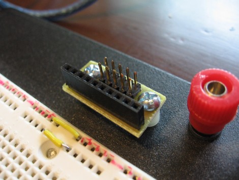
Sometimes we want to sit on the back porch, crack a beer, and do some prototyping. Other times we’d like to do the same but on the couch in the livingroom. To that end we added a 5×2 pin to 10×1 pin patch board to our solderless breadboard.
The 5×2 pin form factor is pretty common, used as an AVR programming header, on development boards like the Dragon Rider 500 and the STK 500, and in small prototyping devices like the Bus Pirate. We like the freedom of using IDC cables as interconnects and that’s where this board comes in. Now we can patch into the IDC cables yet still quickly disconnect them when moving to a different prototyping location. Check out the PCB artwork and this handy device in use after the break.

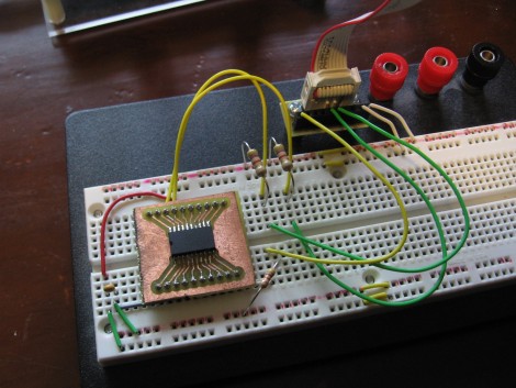
Above is an image of the DS3232 breakout board we made a while back. We have probe cables that we could use to connect directly to the pins on the breakout board but as you can see, we need a smoothing capacitor and three pullup resistors in this circuit so we’re using a breadboard. In the past we’ve connected jumper wires directly to one end of an IDC cable but it’s difficult to ensure you’re made the proper connection and the wires frequently come loose. With our new breakout board attached to the breadboard, solid connects can be made to the 10×1 pin sockets while preserving portability with the 5×2 pin header.
If you want to make you’re own, the PCB artwork is below. We used 6-32 machine screws, nylon spacers, washers, lock washers, and nuts to firmly affix the PCB to holes we drilled in the base of the breadboard. Good luck and let us know how you like this addition.


I just plug a 5×2 header right into the protoboard, problem solved.
^You must have never used a protoboard…
^Maybe he’s thinking stripboard or some such
this required a pcb and artwork?? a scrap of perfboard is more than enough but, .. anyway, .. handy
@Hitek146 it’s a bit tight, but it works.
Nice little utility, what might have been useful as well would be to have a 2nd design that is double sided that gives a pinout for pin headers that straddle the centre gap on the breadboard. wouldn’t need wires hanging off it unless they were necessary. the intial post could also be expanded for any pin configuration you desire for a given application :)
I made my own 2×5 pitch conversion adapter. It consumes some space on the breadboard and having a flatcable in the way, but it works.
Another idea that works is buying a (long pin) male-male pin headers and use female patch wires. You can then easily have multiple sizes too and do real break-outs.
wouldnt it be simpler to use male pins downward instead, so just plug the adaptor into the breadboard and nothing nothing looses connection when you prototype somewhere else (couch)
Edit: Lame , its srewed there, so my post was useless^^
also the problem with stuff that sits ON your breadboard is that it sucks up space ON your breadboard
10 pins may not be much, on the same token I have a ubw32, thats 80 pins and sucks down 3/4 of a normal sized single BB, I have more (not larger I dont need a 1 square meter BB) but thats not really the point
I think its good that the adapter is outside of the breadboard, and maybe you could make lot of those adapters and the board being the same size you could swap them on the board depending on your project.
duckbill pliers… 2 wire-wrap chip sockets… bend one of the sockets to match up with the ribbon header, stick short pins in one of the sockets and use that to plug into the other… use a zip tie to hold the 2 sockets together… plug into breadboard.
crappy cell phone pics of this old kludge…
http://c1.ac-images.myspacecdn.com/images02/149/l_0defc367ecf24f6ea3603ca0f2e5a708.jpg
http://c4.ac-images.myspacecdn.com/images02/128/l_4896834ee0984b3fa890f18ef3c09bb7.jpg
Great bit of design.
I made my own adapter from IDC to DIP so I could plug in my MSP430F2013 to a breadboard, although this is 7×2 not 5×2
http://4.bp.blogspot.com/_RIsp8hACtkg/S9JVhcWaBnI/AAAAAAAAAC0/Fz1LkqTaikU/s1600/DSC_4767.JPG
You don’t need artwork, just an iron. But yeah, it is nice to have it off the BB for the extra room
@Erik: Now I’m fairly certain that you have never used a protoboard…
You see, a protoboard has no location available to accept a 5×2 header with all of the pins being electrically isolated…
If you didn’t wanna bother with a nice printed board, a perfboard with a patch behind the back wouldn’t be too horrible in this instance.