Pogo pins – spring-loaded pin contacts are pretty fun to play with and even cooler when they get used in electronic devices like Adafruit and SparkFun’s test jigs. Check after the break for how these two companies have created their own production hacks.
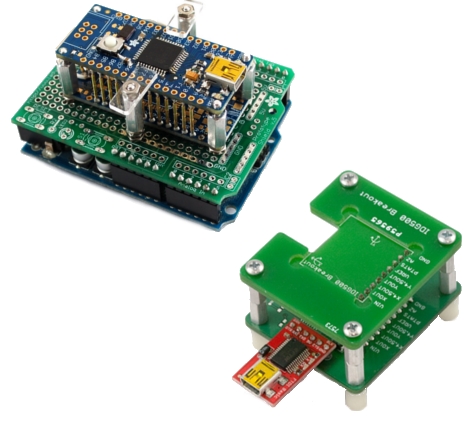
At Adafruit, they build up from an Arduino with a proto shield. An unpopulated board is loaded with pogo test pins and then connected to the proto shield. The board rests on and is aligned with standoffs. The latest Adafruit test jig needs to have an extended test, so instead of mashing a finger against the test board for an extended period of time, they use “ears” to hold the board in place during testing.
At SparkFun, they used to do something similar to what Adafruit is doing now. Now with BatchPCB as the prototyping arm of the company, they make one-off boards for their test beds. For each test bed, three boards are made, all made based on the Eagle files of the board the bed will be testing. The bottom board keeps all of the test pads from the original board and enlarges the holes for the pogo pins, and then adds circuitry needed for the board test. The middle board has enlarged holes for the tips of the pogo pins to just barely stick through and is what the board under test rests on. The top board is just for alignment.
We could see these devices getting extended to having buttons that are pressed when a board is in place so the tests would begin automatically. Add a robotic arm, and the whole thing would be automated. Scale-up the jig for whole panels of boards. We would like to see more of the hacks people make just to make in production.


I made similar automatic tests for Teensy, but using a piece of plastic and drill press instead of fabricating PCBs. It’s pretty easy to just print a copy of the original PCB on a laser printer, tape it to the plastic and center punch each pin. I edit the pads so there’s a tiny white dot in the center which makes placing the center punch easy. Then on the drill press, the tiny drill bit hits each hole nicely.
It takes a little patience to drill tiny holes through a 1/2 inch thick plastic piece. Drilling down a bit, then backing up to remove the material is best, so it doesn’t gum up on the bit. But even going slowly, a chunk of plastic is a lot cheaper and a LOT faster than waiting for 3 PCBs to be fabbed (especially from batchPCB).
To make the test start automatically, I do NOT use a pushbutton. With Teensy, every board has at least 2 Vcc pins. I just apply 40 mV (through a 1k resistor) to one of the Vcc pins. 40 mV is not enough to flow current through any diode junction or turn on any transistor, so unless Vcc and GND are shorted (the reason for the 1k resistor), there’s no current flow.
My automatic start detection looks more more than 20 mV on the other Vcc pin. That other pin has the surface of the plastic machined slightly lower (just chuck a 1/8 inch end mill in the drill press and lightly touch the plastic to take away a little material). The 40 mV is created by a resistor divider, actually with 3 resistors so there’s both 40 mV and 20 mV. I just used a LM385 opamp, and 10K pull-down resistor on the “short” pin. When the user presses the board down, it touches that pin last and the opamp sees the voltage suddenly go from zero to about 40 mV. Opamps like LM385 need a pull-down resistor to make a nice TTL logic signal. Maybe a LM393 would have been easier?
Anyway, if anyone’s looking for auto-start ideas, that’s how I’ve been doing it for testing Teensy for a couple years. Works great.
So… what exactly do these things do? I feel like the author made some assumptions about my understanding that weren’t correct. Any help?
I love it. I remember watching, “How its made” once and they had an automatic jig for testing Matrox video cards using pogo pins.
@Paul
great board, teensy is awesome
waiting on teensy ++ for some fun tests
thanks for sharing :)
Wow those are expensive. Spark fun wants 96 cents a piece for the cheap pogo pins. Worth it guess if you need em.
@confused
The idea is to test the PCB for defects. When you’re producing a decent sized batch of PCBs, there’s a good chance a couple are going to have pin shorts, joined pads etc. The ‘pogo pins’ are spring loaded retractable pins that you can put in a test board and press down onto the PCB you’re trying to test. Since they’re retractable, you can ensure that all of them are in contact at the same time. Each one touches a test point (power, ground, etc) and with sufficient logic on the test PCB you can ensure that the tested PCB is free of defects.
@confused
If you are having a bunch of circuit boards fabricated, you need a way to check that they work correctly. You might test that all the tracks go where they are supposed to by using a ohm meter, but that takes a while if you need to test 100 boards. For larger batches and more complicated projects, you want something more automated. Something that you can just push your new board against, and let a microcontroller do the testing for you.
These jigs let you do just that. Use an unpopulated board to hold the pogo pins and connect them to your testing rig; then just push the final product against it and have it run your automated tests.
Soldering on some pin headers during development, and removing them upon completion really isn’t much of a hassle, but I could see this saving a lot of time if I wanted to quickly program several usb-less dev boards with the same code.
It reminds me a bit of the old solderless mod chips for Xboxen. They weren’t always reliable, but some of the designs were pretty clever.
Oh cool! Those look like the pins used on the agilent ICT machine at work. Although the pins on it are gold plated on the heads, these didn’t appear to be.
@ Paul- Good work on the autostart systems.
SparkFun has a pretty good tutorial on pogobeds: http://sprkfn.com/t/138
@dave
Yeah genius, that’s what they’re linking too.
@NatureTM – Programming code into chips is only part of it.
For products like Teensy, every pin needs to be verified, not just those used to program the code. For Teensy, my test first programs in code that reads all the pins except Tx, and then sends several bytes out the Tx pin at 1 Mbit/sec. It then applies a low to each pin while driving all the others high, and then a high to each pin while driving all the others low. For each pattern, the Teensy is rebooted and the several bytes are read and compared to the correct pattern. If any doesn’t match exactly, the board fails. Actually, the A0 and Ref pins are driven with various analog voltages, and the A/D is used to output 1 byte, which is compared to a known correct value (+/- a couple codes for random noise and settling time, since this all happens pretty quick). Reading the analog result at different ref voltages verifies the analog pin and the ref pin are connected properly, and doing so with all other pins driven both ways verifies no shorting to from those to any other pins.
That may seem overkill, but when you make a lot of boards, a tiny fraction have problems. With Teensy, it’s a little under 1%. Most end up being microscopic solder shorts between pins under the QFN chip. Turns out there’s a shop with an x-ray inspection machine where they can find these and sometimes reflow the solder to fix them. Even if it can’t be fixed, at least no customer will ever get the bad board. Any unfixable but still usable (sans a pin or two) are usually given away at the local Dorkbot meetups here in Portland.
Testing guarantees that when someone buys the board, they’ve got 100% good board that’s had every single pin fully tested. Especially for development boards, it’s critically important that every pin functions. If even 1 pin is bad, it could cost someone a LOT of time trying to debug their code or project.
The autostart feature on the test saves a lot of time while testing. You just press the board onto the pins, and the test begins when that shorter pin touches and all the others have engaged well. There’s actually about a 1/4 second delay to allow that last pin to engage well. I’m not sure why some tests are so slow… I use heavily optimized code on the tester, so the entire test takes under 1 second. Either a green or red light turns on.
Here’s a copy photos of the first Teensy 1.0 tester, taken about 2 years ago:
http://www.pjrc.com/teensy/beta/tester1.jpg
http://www.pjrc.com/teensy/beta/tester2.jpg
That http://ladyada.net/make/pogojig/ is chuckfull of 404 picture links.
@confused – in case you didn’t get what exactly pogo pins are, they’re little spring-loaded contacts. Put pressure on them and they shorten smoothly, maybe up to 1/4″ or so for larger ones. They let you make a solid, but temporary, connection.
Pogo pins tend to be obscenely expensive through regular outlets. I happened to stumble across a booth full of them at the SEG Electronics Market in Shenzhen and stocked up – probably spent the equivalent of $20 for a couple of bags of them.
Even better, I found a place that makes fixtures. Now, if I want a fixture for doing hundreds of boards, I send them a sample and the Gerber files and some notes about my requirements (through an intermediary since no one there speaks English or wants to deal with international shipping) and I get back a fixture with alignment pins or a milled bed, switches, and a big lever that lowers the top half and engages all of the contacts.
Last time I got one, it cost me about $150, including shipping. The pogo pins alone in that thing would have cost me $80 domestically.
Can you share the contact info for the test jig company?
I don’t think they’re doing small quantities anymore. There are probably others at SEG, but I haven’t been there in years. If I ever had their direct contact information it was on a Chinese business card. I only had contact with them through my driver/translator.
Wow! Thanks very much for the article.
I recently found the test-jig info on Sparkfun.
But now I can compare the jig methods of the two companies for more methods and inspiration.
Thanks Hackaday!
>>That http://ladyada.net/make/pogojig/ is chuckfull of 404 picture links.
@Whatnot — try again, I got 12 really great photos, each with regular and higher-res pictures.
@leef_me Still some dead ones, like the 3rd and 4th that goto:
http://ladyada.net/make/pogojig/Documents/ladyada_net-www/ladyada_net-www/images/pogojig/victim.jpg
and
http://ladyada.net/make/pogojig/Documents/ladyada_net-www/ladyada_net-www/images/pogojig/pogo.jpg
And that are dead links.
I tried to look for some pogo pins here in Europe, but couldn’t find any until I came across some pins called plungers over at Farnell:
http://nl.farnell.com/multicomp/p100-h-250-g/plunger-serrated/dp/1568268
Looks like the same stuff, and not too expensive. Can anyone elaborate on these? And which tip style to choose for which application? They have serrated ones, pointed ones and concave ones.
@David
I’m no expert, but in my experience you use the serrated ones to contact holes, the pointed ones to contact pads, and the concave ones to contact pins.
If you use the pointed ones to contact holes, they tend to get stuck. You want a wider tip for that, and I’m guessing the serrations help cut through any surface oxide layer to make better contact.
One of my fixtures mates with through-hole DB9s on the board, so it has concave tips to receive the pins.
Also, the receptacle that the plunger goes in is probably sold separately. The ones I got in China were all wire-wrap types, and despite having never done it before (and having to buy a tool that’d been on the shelf in the local electronics shop since about 1979) I found that I really like wire wrap for that sort of thing.