
Electronic musical instruments are a lot of fun for a hacker because, with a small palette of tools, know-how and curiosity, they are easily modified. As with any hack, there is always the chance that the subject will be ruined, so it’s not necessarily worth the risk to muck about inside your thousand-dollar pro synthesizer. Luckily for all of us, there are shovel-fulls of old electronic musical toys littering the curbs and second-hand shops of the world. These fun little devices provide ample opportunity to get familiar with audio electronics and circuit bending techniques.
A note on definitions: the term “circuit bending” can be synonymous with “hardware hacking” in the world of audio electronics, and we have seen some debate as to which term is better suited to a given project. We welcome you to share your viewpoints in the comments.
Keep reading to get started.
Materials
So, you’ve heard of circuit bending and you want to give it a try eh? Well for this introduction, you’re going to need at minimum the following materials:
- electronic musical instrument (the bendee) with batteries or AC adapter
- alligator clips (for temporary connections)
- various resistors and/or a potentiometer
- ears
and it’s a great help if you also have:
- oscilloscope
- bench-top power supply
- camera
For our first attempt at circuit bending, we will be using a Yamaha PSS-14 keyboard. We found it by the side of the road, abandoned and lonely and without a friend in the world. Like mad scientists conducting mad genetic experiments on lonely abandoned animals, we will rebuild this poor creature to be better, stronger, and stranger than before!
Background Research
Thanks to our high-fallootin’ academic standards, we’ll start by researching a little bit about the keyboard in question. The more adventurous among you can skip this step and dive straight into the fun part. From Yamaha’s site, we can see that this model sports “100 Advanced Wave Memory Voices”–that’s their hilarious marketing term for “100 Pre-written Sound Files”–making this what’s known as a “Wavetable Synthesizer”. Wavetable synthesis is a very easy and cheap way to create sounds because you can simply copy a bunch of sounds to the memory of the chip and then read through them sample-by-sample, changing the sampling rate to change the pitch (or having separate samples for each pitch value, depending how much memory you have to play with).
Further research reveals that we’re not the first to circuit-bend this particular keyboard. This example and also this one show some interesting possibilities, and by the end of this article we’ll have a better idea of what they’ve done. But enough talk, let’s crack this baby open!
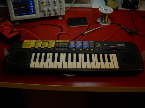
Here we see the PSS-14 in its original state: operational, but missing the case screws (it was held together by duct tape when we found it). Perhaps a previous owner did some exploration of their own?
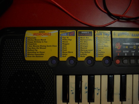
The preprogrammed songs cover all the major categories of music: Memories, Cool&Hot, Favourites, Fun Time. When we were younger we used to listen to Cool&Hot music all the time, but then it got mainstream so now we’re mostly into the underground Memories scene. You haven’t lived ’till you’ve heard the new remix of “Gallant Pig”.
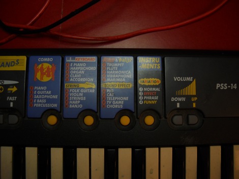
There are twenty keyboard-controlled voices to choose from, most of which sound about the same. The volume controls seen here make a very loud “bongo” sound when you press them, no matter if the volume’s as low as possible.
Look Under the Hood
Clearly this thing could be better, so let’s open it up and see what we can improve about its operation.
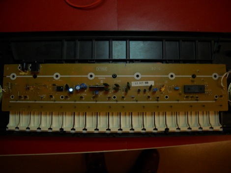
The circuit board under the hood is pretty sparse, which is somewhat unsurprising seeing as it’s a wavetable synth and therefore most of the fun stuff is taken care of inside the microcontroller seen on the right. If you can find old electronic musical toys from before the digital era, you have access to a lot more of the nitty-gritty sound generation. Unfortunately those are much harder to find on the side of the road.
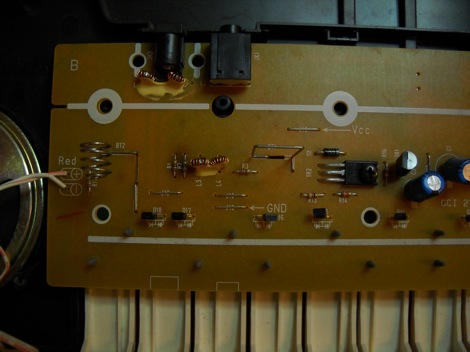
On the left side of the circuit board we can see the clearly-marked Vcc and GND connections, which would be easy enough to find from the battery terminals. The keyboard takes 4 AA batteries, which means it runs on a 6-Volt supply. We didn’t have the AC adapter for this keyboard so we’ll run it off of our bench-top power supply for now.
This hardly needs to be said but BE REALLY CAREFUL if you are going to use an AC-powered device. The bench-top supply we’re using has a current-limiter but a wall-wart transformer can push dangerous crowds of electrons through your body, which we understand to be an uncomfortable experience.
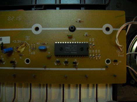
On the right, we can see a bunch more resistors and–the holy grail–a clock component (it’s the blue blob to the left of the IC)! On digital synthesizers this is generally the main source of fun.

In the middle of the board there is a cluster of capacitors and what looks like a multi-transistor package. When we turn the board around and start probing, we’ll figure out what this is all about.
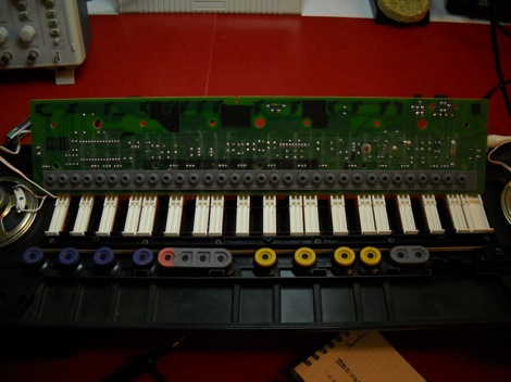
The soldered and printed side of the circuit board is much more interesting to look at. The dark patches that you see are conductive ink–this is a really common and cheap sensor technology used in everything from the humble NES controller to high-end Roland electric pianos. It’s a form of what’s known as a force-sensing resistor (FSR) and it suffers from major nonlinearity, hysteresis and repeatability. On the other hand, it’s dead easy to implement and it can be printed onto a board.
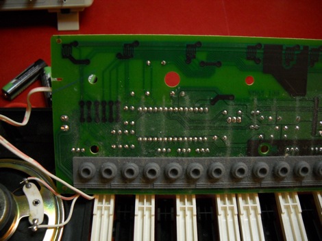
On the underside of the CPU we can start to characterize the pin functions. A lot of the pins go out to the various keys and buttons. A lot of those transistors that we saw topside are dedicated to this key matrix, too.
Scope it Out
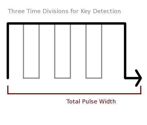
Upon further investigation the button/key states are time-division multiplexed onto pulse wave signals based on a global excitation, illustrated here. According to this fellow who lists a circuit-bent PSS-15 (same model as this but with a silver control panel), connecting part of the audio output to the keyboard matrix returns can re-trigger buttons or keys to make “loops”. Very interesting, seeing as:
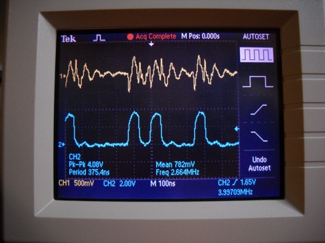
The keyboard uses a PWM-based DAC scoped here in comparison to the audio output further down the line. Again this is a very cheap technology (you can make one for your arduino pretty easily) and you can get a simple explanation here. Right off the bat we can see that a disadvantage to this technology is that its transition times between various voltage levels might be difficult to control, possibly leading to distortion. That aside, it will be interesting to connect the PWM DAC output to one or more of the keyboard matrix returns.
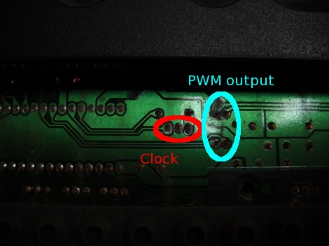
Here is a closeup of two interesting “hack points” on this keyboard. We’ll change the resistors on the right to see what it does to the signal, and we’ll change up the existing 8MHz clock for a different one.
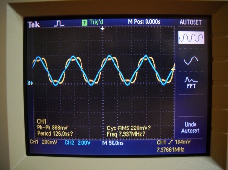
The sine wave oscillations of component CL1 can be scoped to show a transformation into square wave, which we can safely assume is driving the operations of the microcontroller.
Modifying the Circuit
It just so happened that we had a spare 3MHz oscillator sitting around, so let’s find out what happens when we drive this device at 3/8ths of its normal speed.
[youtube=http://www.youtube.com/watch?v=ID6JdjH8gk4&w=470]
A quick and dirty soldering job gives immediate results. In the video you can hear the results with the new clock and changing the resistor value at the PWM output–overdrive city!
[youtube=http://www.youtube.com/watch?v=rtJtg8AhMFY&w=470]
Furthermore, by patching the audio output to parts of the keyboard matrix, we can create the “loops” as discussed eariler.
The results thus far have been, well, a little underwhelming. We can make the sounds slower and we can make little loops, and we’ve learned a little bit about consumer-level electronic toys. Still, at this point we were hoping to have unlocked some seriously badass digital fury.
Serendipity came to our help at this point, and an inadvertent touch of the oscillator legs produced the righteous vibes we’d been banking on!
[youtube=http://www.youtube.com/watch?v=BCYwfa5n4lE&w=470]
The sounds that came out of this thing were incredible. Somehow, after assembly, this type of thing was happening at startup and it’s now only about a one in ten chance that the keyboard boots properly. Even then it’s at running 3/8ths speed… except some of the time, somehow, it properly adapts the PWM output so that despite the underclocked CPU the wavetables read at the original sampling rate. Who knows what is going on that ASIC.
What to do with it now?
At this point in our circuit-bending adventure we’ve characterized the operation of the device and found a couple of fun bends. Where to go from here? Well, one option would be to make the modifications permanent with the addition of pots, buttons, patchbays and what-have-you so that the end result is a sleek and performable instrument. We’ll be saving for a later date. Since, as we mentioned at the beginning of the article, it is quite possible to destroy a hacked piece of electronics simply by virtue of the stress caused by the modifications themselves, we’re going to finish this bend by recording the myriad new sounds that the keyboard produces, and composing a short celebratory piece of music:
Summary
While you may not have this exact toy keyboard at your disposal, the same techniques and methodology used here can be applied to many other audio devices. It’s simply a matter of
- Taking your time
- Understanding the technology
- Characterizing the circuit
- Experimenting
At the end of the day it’s not really that difficult to get started at this sort of thing–hopefully the concept of circuit bending has been demystified for some of you. This isn’t to say that circuit bending can’t go deeper than shown here, as this only shows the most elementary steps. And the complexity of the device you’re working with greatly affects the types of bends you can do–for example, the TR909 has many timing circuits that can be played with in much the same way as our Yamaha. We’ve recommended it and we’ll recommend it again, but for further reading be sure to check out Nick Collins’ Handmade Electronic Instruments. It contains a good section on toy hacking, and it’s generally a very good read.
If you enjoyed this introduction and want us to write further articles exploring different parts of circuit bending (or audio hacking in general), please let us know in the comments.


I love circuit bending. I did a Speak & Maths a few years ago. Great article, and love that tune at the end. Instant Aphex Twin or Squarepusher. More please.
Haha, I like how you preempted the debate on the terms “circuit bending” vs. “hardware hacking.” It seems to be argued about every time. I would say circuit bending is a subset of hardware hacking. Still, I can’t help but picture a kid touching wires randomly around a circuit board when I hear “circuit bending.”
Mahalo.com has blocked the first video, whoever went after them last time they started doing that didn’t do a good enough job, it seems.
Great intro to circuit bending and that tune at the end was unexpectedly good!
Nice introduction to circuit bending! It would be nice to replace the synthesizer IC with a fast, programmable MCU, and make it a drum machine.
Article starts out slow and then quickly jumps to conclusions. I don’t really care where you found the instrument, instead I would have liked to know how you found the PWM pins, figured out the keyboard matrixing etc.
I agree with Nemo. good introduction, gives a primer for those interested in hacking the hardware in a musical keyboard. this is one step closer to shutting me up for good. i would add one thing to the list of requirements: MUSICAL TALENT!
all this effort if you have no ear for music is a waste of time. i was surprised at the tune as well, it had some musical quality, i would encourage the person who made it to do more, maybe study music styles, etc.
i know this opinion of mine will no doubt enrage more than a few people, if so i apologize, but that’s all it is, OPINION.
Tune at the end was great! Circuit bending is loads of fun, also look into simple toy voice recorders, they do some crazy stuff!
circuit bending = the very beginning of hacking, as far as i’m concerned. my favorite pastime from ages 2-infinity
i like to experiment with the circuit between the guitar jack and the amp, which, in my case, is just two wires so i will throw some random shit in there to see if i can make it sound better, or make a new effect. idk what’s up with my guitar though sometimes i have electrified strings that shock you. probably because of my lack of observation of polarity
yea stoped reading after your parent company blocked its own content
stupid
@ALL about the video,
It blocked, then unblocked… now it looks like some of you are seeing it blocked again? …grrr :/
trudat
Nice sounds!
I think that if you are joining random contacts to random components, you should call it circuit bending.
If your modifications are not (totally) random, you can call it hardware hacking.
I would like to read more (and more detailed) articles like this!
I have an old CASIO keyboard that uses the same conductive ink for its keys, but some seem to have worn out….. any ideas where i could buy some or if there’s some other sort of conductive material that would work instead??
got an old 1980’s Kids Casio keyboard with inbuilt beat generator; gonna fire it up when I get home and start prying!
Any news on that? I know I’m seven years late, but who knows.
most of what you want to bend is usually the clock and rom if there is one
most of the time people go overboard though and end up with it broken
even with modest bending it can eventually break it
my advice would be to bend it and take samples of what you did
also use batteries insted of adapter if you can
circuit bending involves some jackass who takes a bunch of his child’s old toys and randomly shorts out and applies excess voltage to them in an effort to make horrible distorted noises and calling this sucess
What D said. Circuit bending involves some jackass destroying vintage technology in order to make something that sounds like shit.
anyway hardware hacking or circuit bending both means patience
working now Caleb
If the circuit blows you can always bang the thing on the table or break it and make scratch noises with the parts, seems awful noise is the purpose anyway.
…
More please!
…
Moist fingertips! Defining this is hard but resistance changes this way is the way to start. Then wire in a high resistance pot. Not rewired but bent.
Peanut: Check out the liquid wire from thinkgeek.com then find a toothpick and some patience ;) I hope this is the right kind of contact I am thinking about. You may be able to get by with dielectric grease also. Casper electronics may have a good tutorial as well as Sailormouth. http://www.casperelectronics.com/ and http://sailormouth.org/ on getting keys working again-they are kinda the guys I follow. ALso check out http://weltenschule.de/TableHooters/instruments.html for one of the most comprehensive histories and chip lists of all the lil dinky keyboards that we all love so much :) Just sad I have some more folks to do battle with at the thrift stores and yard sales, but always fun to see folks get into circuit bending :)
THANKS CALEB AND CREW FOR THE ARTICLE :) MORE :)
@Peanut
Car defogger/defroster repair kit — get it at any auto parts store.
I’ve repaired dozens of TV remotes and game controllers throughout the years with this stuff.
Radio shack also sells an overpriced “trace repair pen” that contains the same substance.
Really don’t understand the hate for circuit bending.
Messing around with stuff to make it do other stuff is kinda like hacking, isn’t it?
So what if you don’t like the noises they make?
I’m sure some folks hate it when things are made to spew fire too.
I’d just tell those folks not to look.
“hacking”, make something do something it’s not designed to do – circuit bending is just an artsy fartsy way of saying “hacking”.
Audio circuit hacking is fun! I love how it suddenly, violently plunges the known into static random sequences of unknown. That’s the fun of it for me, not knowing exactly what’s going to happen. Each modified device has its own personality and style. Compare the Casio SK-1 with a Yamaha PSS series for example. Getting into a deep crash state can yield some of the most amazing sounds. Just don’t forget to hit record. Like the tunes and definitely want to see more content like this, particularly bridging the gap between “engineering” and “tweaking”, such as your analysis with the oscilloscope. Great stuff!
“A note on definitions: the term “circuit bending” can be synonymous with “hardware hacking” in the world of audio electronics”.
WTF??!! Are you kidding me?
Circuit bending is based on chaos. Some kid licks his fingers then fondles the innards of his speak-n-spell to see what kind of unique noises come out. If it makes a cool sound, he or she may add switches between these points so they can be accessed later, while performing. Some circuit benders even create external patch points instead of switches. The possibilities are virtually limitless, and circuit bending is pretty cool, but it’s not anything like hardware hacking. Also, circuit bending is typically performed on low-end/toy instruments. “Circuit bending” expensive professional instruments, such as vintage synthesizers/drum machines, is called Butchering, and it’s far less cool.
Hardware Hacking, in the audio electronics world, is a skill requiring knowledge and discipline. The goal is not to simply make the instrument sound unique by randomly connecting points within the instruments circuitry. Hardware hacking begins with a deep understanding of each circuits function. Once the circuit is understood, the hacker figures out how he/she can add established features and familiar parameters to expand the flexibility of the instrument. An example would be to add an LFO to an analog synthesizer which does not offer this feature natively. Another popular hardware hack or mod is to make an instrument modular via patch points. While circuit bending would be content patching any point within the circuitry to any other point as long as the resulting sounds are interesting, hardware hackers have a more disciplined approach. For example, a hardware hacker would add patches to practical points, such as inputs and outputs to and from VCO, VCF, VCA, EG, LFO … etc. Modding in this way allows another musician who may not understand electronics but is familiar with analog synthesis to know how to utilize these new patch points and/or new parameters based on their labels.
Please, you guys, don’t get it twisted.
I’d like to see more of what the oscilloscope can do and more detail on how it was used in this hack.
I love this hack! Might do something similar as an addition to my other /to-build/ list.
@Alpha knowing the nomenclature doesn’t change anything. There are plenty of “hackers” that are posted on here daily that don’t know electronics so they use an arduino. Likewise there are many circuitbenders that use 555 timers different and crystals to add sequencing or change the system clock. It all sounds pretty twisted…
@carbuncle I agree. Knowing the nomenclature obviously doesn’t make one a hacker. Hackers create modifications which can be utilized by non-hackers who know the nomenclature. Circuitbenders create modifications that are, at best, difficult to define. Therefore, one can’t use a circuit bent instrument correctly or incorrectly because a system of rules of conduct or method of practice simply is not present.
As for circuitbenders using 555 timers, crystals and the like, those guys are bordering on being true hardware hackers/modders, or at least “hardcore” circuitbenders.
My point is: circuitbeding is in a class separate from hardware hacking, or at least a subset of hardware hacking. I’ll never understand why this line is blurred when dealing with audio. If one was to haphazardly play connect the dots inside of a computer just to watch the sparks and puffs of smoke, would that make them a hacker? While a circuitbender may not mind being called a hardware hacker, a true hardware hacker doesn’t care for the confusion. It’s like calling a janitor a chemist because he works with chemicals.
I guess at the end of the day, bending/hacking/modding etc. are different flavors of renegade art forms. With that in mind, solidifying classifications and labels will always be a challenge. But, it doesn’t hurt to try.
As for Arduino, I can’t knock them when used in a practical way. However, too many “hackers” use Arduino as a crutch, or a way to side step certain disciplines because the user is too lazy to learn. You really can’t blame the platform for that.
Exactly! It’s like calling “IT” computer science or engineering. Same idea with the janitor and chemist…..
I love how some of you have such a harsh view on circuit bending in general. I guess you think unless if something is perfectly planned and organized, it’s blunt and brutish. I’m sorry that you can have no appreciation for sound collaboration and just having fun. I’m sorry that you feel the need to be right in every last little thing you do to boost a crippled self esteem. Most of all, I’m sorry that you fail to grasp what can be art, and that art is whatever you consider to be art. You don’t get to control the universe, and you don’t get to control peoples lives. Stop taking a dump on other people’s fun.
Don’t forget the pioneers:
Reed Ghazala: https://secure.wikimedia.org/wikipedia/en/wiki/Reed_Ghazala
:)
I’d like to see more of an article on what they do to the harsh chaotic sounds to make them into something as listenable as the final tune, it’s all well and good making your synth sound like a car crash but making it sound good afterwards has got to be 50% of the skill :)
@Marco
I could have gone into more detail about how I sussed out the keyboard matrix and DAC operation: my method was simply to scope each of the pins of the microcontroller and note down its probable function. The buttons were easy enough to trace visually as well, and the TDM encoding became apparent when several buttons would activate the same pin. The PWM DAC was the only part of the controller that was connected to the amplification stage of the circuit.
@Reggie
In this instance I made sure not to overly process the sounds, just a little bit of cropping, and the arpeggio line at the end is the same sample pitch-shifted in much the same way as changing the clock speed. I wanted to leave the sounds mostly unprocessed to demonstrate that the output of the keyboard is fairly rad as it is.
The major difference is really in the arrangement and mixing, which I couldn’t have done on the keyboard itself (the good sounds all came from crash-states). What I’m saying is, you don’t have to be a musical or DSP genius, trust your ears and have fun!
FYI I used Renoise for sequencing.
I feel like to truly understand circuit bending, we deserve a discussion about the difference between music and sound art.
nice tune! see if you can make a longer one!
I always thought the term circuit bending originally came from weird sounds you get physically bending/destroying the board and, was later adopted by hardware hackers
great music!
This is a pretty good introduction. You know, the PSS-14 is one of those keyboards that I’ve seen many circuit benders dismiss as “unbendable.” Mentioning the oscillator is an important thing that circuit bending tutorials often forget…
Try getting a PSS-130 and replacing the clock oscillator with a 555. Use 1K resistors and the smallest ceramic cap you can find. The range at which that chip is stable is unbelievable for a toy. You can do virtually anything with a much higher or lower clock speed that you can do with the original oscillator. It will eventually crash at the highest speeds the 555 can achieve, but I haven’t been able to crash it by underclocking at all.
Cool response! This is something I would love to try out. I am currently bending a kawai fs690 but I am having trouble manipulating the clock. NONE of the solder points will do anything but short it. I can only take the clock down by connecting my finger to it. Do you perhaps have any experience with the kawai keyboards?
Thanks
nice.
Thanks for the circuit.
@D and @TheMoogle need a hug.
My favorite thing about circuit bending is the act of taking a dated, often dejected piece of electronics and instilling a new life in it. I like the sound of digital chaos. I’m not saying everyone else should to, but by saying that those who do are jackasses, you become one yourself.
Also, live noise shows are possibly the most cathartic activity possible.
bending/hacking/modding etc. are different flavors of renegade art forms. With that in mind, solidifying classifications and labels will always be a challenge
Thanks
Don’t let the dinosaur’s and sticks in the mud discourage you. Don’t let their petty arguments about terminology, or the condescension in some of these comments dissuade or intimidate you. Their comments are inane.
Using the same logic, someone could say that programming a Korg MS-2xxx or similar synthesizer isn’t “really” programming, because any idiot can plug a patch cable into two different ports and make a shitty sound. The thing they forget is that sometimes, you might also make a really kickass sound…
Once upon a time, there were people that spent a great deal of time berating those that connected the familiar piano-style keyboard to a synthesizer.
Screw anyone that tells you it’s garbage just because it isn’t done “right.” I’ve heard amazing patches written on an iPod touch in a DAW. One of the best bass drum sounds I’ve ever heard was an old metal water barrel barely modified and integrated into a drum kit. Conversely I’ve seen people spend thousands of dollars on synthesizers or other gear, and they only use presets because they can’t make a patch that sounds decent.
Experiment. Play. Realize you will probably fuck up, and don’t be afraid to do so. Learn from your mistakes, and be careful.
You’re creating potential tools here, that is all.
Fascinating stuff, please keep me in the loop!
Hmm. I was hoping for advanced flexible pcbs.
Audio? Then maybe warping a steel guitar string or string on a fret, or a musical saw. It sounded as if ine commenter had Jimmue Hendricks ir at least LSD in his mind… playing under the influence.
What if key A and A major produces same sound together on pressing either in all octave.