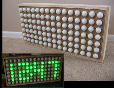
If you’ve been lusting after your own glowing display we’re here to help by sharing some simple building techniques that will result in an interesting project like the one you see above. This is a super-accurate clock That uses ping-pong balls as diffusers for LEDs, but with a little know-how you can turn this into a full marquee display. Join me after break where I’ll share the details of the project and give you everything you need to know to build your own.
Planning

Take some time to sit down and figure out how many pixels you need in your display. Above you can see the sketch that I drew on the back of some junk mail. Since I need a clock for my shop I’m only going to include LEDs for a twelve-hour time display. But I did plan to populate the entire grid with diffusers (ping-pong-balls) because it will look a bit cooler that way. I also planned to include a ring round the entire display so my final pixel area will be 15×7. Note the numbers below each digit, which are an LED count.
I also did quite a bit of planning at this point for the electronics. I need to make sure that I’m handling the current properly so that I don’t burn out any of the LEDs or chips that drive them. For now, let’s skip over the electrical issues and build the actual display.
Materials
First you need a box to host the project. I chose to use pegboard for the clock face because it already has accurately spaced holes that fit a 5mm LED quite snugly. The pegboard will be wrapped in a plywood frame which gives it strength, protection, and a place to mount the buttons and other hardware. You’ll also need all of the LEDs for the display (46 in my case) and ping-pong balls for the grid (105 in total).
From the start I wanted to complete this project with parts on hand. I already had the scrap of pegboard, and the plywood left over from building a wall-mounted desk for my office. Most of the electronic hardware was salvaged from another project (more on that later) and in the end I only had to buy ping-pong balls, hot glue, and some mounting hardware for the buttons. Here’s a list for the display itself, excluding the controller board and buttons:
- Pegboard for the face
- Plywood for the frame
- LEDs
- Ribbon cable
- 22 gauge hookup wire
- IDC connectors
- KK connectors or another 0.1″ pitch connector
- Woodworking tools: table saw, circular saw, straight edge
- Pocket screw jig and pocket screws
- Hot glue gun and hot glue
- Soldering supplies
Assembling the case

I first started by taping out the digits on a piece of pegboard, then clamped a straight edge along the cut lines and used a circular saw to trim it to size.

Pegboard is usually a bit flimsy so you should build a frame around it to make it rigid. I’ve just got some rudimentary woodworking tools so I’ve ripped 3″ plywood pieces, cut them to length with butt joints, and then cut a dado the width of the saw blade to receive the pegboard.

I bought this Kreg pocket screw jig when I was building my desk and I love it. Here I’ve cut pocket screw holes into the ends of the long rails. They butt up to the side rails and two screws will hold them nice and tight. You can get this jig for around $20, but if you don’t want to spend the money just pre-drill and countersink some holes from the outside and use wood screws to hold your frame together.

Here’s the outside of the finished box. All-in-all I’ve put about 90 minutes into the project. The majority of the time was spent measuring carefully, which you should take seriously. One wrong cut could cause an impromptu field trip for more supplies.

There’s plenty of room inside for the wiring and controller board. Now to start inserting the LEDs.

I had a great time building the LED Jack-o-lantern but that hardware has gone unused since Halloween night. Here I’ve desoldered all of the components from the protoboard and clipped apart all of the LEDs, separating them by color. I’ll reuse all of the green LEDs, the transistors, pin headers, some resistors, and many of the longer wires in this project.

Start by pressing the LEDs into place on the back of the pegboard. They’ll be quite tight and I found this process made my fingers hurt after a while. I checked each LED using a battery and resistor to make sure I had the polarity right and that they all worked and were the same color. Above I’ve started soldering all of the cathodes for each LED using ribbon wire. The cathodes are grouped by digit, and will be connected to ground by way of an NPN transistor.

Here all of the cathode connections have been made. I’ve used hook-up wire to run each of the four buses to one side, and inserted them together into a 4-channel KK connector. This will make it easy to plug the low end of the digits into a pin header on the control board. Don’t forget to hot-glue these wires to the pegboard as a form of strain relief.

Now it’s time to solder the anodes for the same pixel in each digit together. I used the waste pieces of ribbon cable from the last step in the process to do this. In the upper right you can see two ribbon cables which have IDC connectors hanging over the side. The top bundle drives seven of the 13 LEDs in each digit. The bottom bundle drives the remaining six. These will plug into double pin headers on the driver board, connecting the pixels through a resistor to a pair of shift register. The colon in between hours and minutes has been grouped with the hour-tens digit which only has pixels for the numeral 1.
Now it’s time to make sure everything works. We do need to add ping-pong balls as diffusers before the display will be finished but if there’s a problem you don’t want to have to remove the balls to fix it. Let’s build and test the control circuitry now.
Electrical Design
I wanted to use parts on hand for this project. I’ve got plenty of 595 shift registers but there’s one problem with those; the supply pin has a 70 mA absolute maximum rating. I can get around that limitation if I run my LEDs no higher than 10 mA each and split the 13 total pixels between two shift registers.
That takes care of the high side. To switch the low side of each digit I’ve sourced 2N3904 NPN transistors. They have a collector current limit of 200 mA which will have no issue sinking the 130 mA max coming off of a digit when the numeral 8 is displayed.
The multiplexing is handled by an ATmega168 running on the internal RC oscillator at 8 MHz. This makes it a breeze to drive the display without any visible artifacts, but it’s lousy at precision time keeping. I had a Maxim DS3232 real time clock on hand that will keep very accurate track of time. It has a backup battery which will keep time when power to the display is lost. This is perfect since I intend to power this from the bench outlets in my shop. I turn them off when I’m not working and that means the clock will only be illuminated when someone’s there to see it.
This how-to is intended to focus on the physical build and not the electronic design. If you make your own it would be much better to choose shift registers that offer constant current on each pin. This way the LEDs can be brighter and there’s no need to worry about pushing up against the current ratings of the shift registers. Most constant current drivers are low side, which means you would then use P-channel MOSFETS, PNP transistors, or similar to switch the high side of each digit. Basically the opposite of what I’ve done here.
Check out the LED pumpkin matrix for more on designing your own multiplexed displays. As for constant current drivers, there’s some nice hardware used in this whiteboard/LED marquee project. Just don’t feel locked into Maxim parts as they can often be difficult to source.
Building the controller

Having designed the circuit it’s just a matter of wiring it up and writing some firmware.

Here’s the breadboarded circuit. You can see the two IDC connectors jumpered with resistors to the shift registers on the breadboard. The yellow wires to the right connect the digit cathodes to their respective transistors. In the foreground is the DS3232 on a breakout board. You can see the coin cell in its hacked holder. I’m using a multimeter to measure the frequency of the 1 Hz square wave this chip provides, and a Bus Pirate to see what’s going on with the i2c communications. Now that it’s working, I just needed to find a more permanent solution.

Voila! The top of the finished controller board. Note the two pin sockets to received the DS3232 breakout board.

And the point-to-point soldering on the bottom. This took perhaps four hours to complete. It’s winter right now and I don’t like using Cupric Chloride inside to etch circuit boards so I went this route.

The last piece of the puzzle is adding buttons. I knew I had this old circuit board from a Sony shelf stereo system.

I needed four buttons so I used a Dremel to separate this segment from the larger board. I added two holes to use for mounting and soldered wires (reused from the pumpkin) terminating in another KK connector.

Here’s a view of the underside of the button board. I had to remove the resistors that connected the buttons into a matrix and I used hot glue for strain relief.

After a trip to Ace Hardware I was able to install the button board. I started by tracing the location of the buttons on a piece of paper, then using that as a template to drill holes through the top of the plywood case. You can just make out the ragged hole above each button.

While and the hardware store I picked up a dowel as well. Here I’ve cut it to length, eased the top edge with some sand paper (I spun the dowel in a power drill for that), and added a hole for a retaining pin.

Once installed I glued a finish nail into the hole of each button dowel so they won’t fall out.

Here’s the finished product. I love it!

Everything’s working, time to add the diffusers. I originally planned to buy ping-pong balls from the dollar store but they only had six 9-packs. I ended up ordering a gross online. I drilled a hole in each ball for the LED to stick through, then used hot glue to attach them. Make sure the drill bits you use for this are nice and sharp.

Here’s a test with the lights on.

And another with the lights off.
Conclusion


I’m quite happy with the way things turned out. If you build one yourself take into consideration the use of constant current LED drivers as I mentioned before. Also, I had crystal clear LED packages, you may want to experiment with diffuse packages. You can see that there is a bright point on the top of each ping-pong ball because of this. On the other hand, in bright light you can still make out the time because of those bright spots, so test this out before you purchase all of your parts.
When all is said and done the display portion of this was easy and quick to build. It took much longer to solder the control board and to finish writing the firmware. A link the git repository is included in the resources section below.


I’m just starting my next project and wanted to get my ATmega168 back. Since I’m only using 2.6k of programming space I can easily swap out a pin-compatible ATmega8 which I have on hand.
I’ve branched the code and have the chip in and working. I also discovered a bug in the Timer2 ISR (TCNT0 should be TCNT2) which fixes the bad button debounce I was experiencing.
I’ll clean up the code and push it to the repository soon.
Cool project! Must look cool on a wall!
Quick tip: Drilling into ping pong balls is hard. Melting them is easy. Best way to do it is to heat up a screwdriver or drill bit (held in pliers) over a flame and use it to poke a nice easy hole in the shell.
I drill plastics in my cnc machine shop
frequently. The technique that is
successful in most plastics is to
change how the bit is sharpened by
dubbing the front rake angle to zero.
Normally, the front of a drill has a
positive rake angle, dubbing is
changing that rake angle to neutral
(so the newly sharpened front face
of each flute is parallel to the length
of the drill). easy to see, hard to put into words. Wish I could upload a picture.
This resharpening is also what you do
for best drilling in dis-continuous materials
such as brass. It also prevents the
“pull-in” effect when you break through.
I was taught this by an old machinist when i was young in the trade.
Here’s how I did it – http://www.jcopro.net/2011/03/31/how-to-make-a-hole-in-the-middle-of-a-golf-ball/
-See the end of the post
Try to file the tip of the led so that it doesn’t project a dot on the ball.
Why use whole balls? Halfs should do as well i suppose
MotherTrucker! I’ve been tossing around this very same idea in my head for a couple months now, but haven’t had time to do anything about it! Well, it’s a really nice project!
Looks like the project I’ve been meaning to get to. On one of my last orders to mouser I got about 500 LEDs. I’ve built about 4 8×8 matrix displays on protoboard but I’ve been meaning to build a large scale one just like this.
Nice work! A diamond coated dremel bit works really well to frost the leds prior to inseting them in the pingpong ball. Also a step bit such as a Unibit is good for nice round holes, after you drill a pilot hole. I’ve found brad-pointed twist drills work well in other plastics, never tried one on a ping-pong ball, but may also be good, and a lot cheaper than a Unibit.
I built one of these back in the late 70’s. Instead of LED’s, I used actual 110 volt 40 watt light bulbs switched by relays driven by optoisolators that in turn were switched by TTL logic using a MOSTEK clock chip (can’t recall what model I used at the time). It worked but was more a college project/experiment.
An early prototype computer used this for it’s
display.
It’s a shame it is crippled by the Middle Ages mindset of 12 hour notation. The Romans didn’t use zero and thus couldn’t count.
I use 400grit Wet & Dry sandpaper for rough up the LED surface. it makes the balls glow nicely.
I hope people are using super cheap plastic ping pong balls instead of celluloid ones. Otherwise it’s like keeping a kerosene soaked rag on your desk.
And why would an LED in a celluloid ping pong ball be similar to a kerosene soaked rag on a desk?
FTW!!! This is absolutely beautiful, awesome and fantastic. Until you have to clean the dust off.
Shove the entire thing behind well-sealed glass and ftw.
I love the melting idea.
Also love the various diffusion methods to kill that hot spot.
I kinda like the diffusion effect from ping pong balls. It works well and looks cool.
Rad Shmack sells a 7-color LED that I’m fond of building little stupid projects with, and I bought a bag of ping pong balls at the store after reading this article.
Very cool ideas. I love HAD for stuff like this.
What is the IC2P and IC3P on the schematic? I’m trying to learn how to use eagle and i don’t see where those Nets go to?
@Alan: Those are the two shift registers. Note that on the schematic symbols for those chips there are no voltage and ground pins. Those pins are hidden by default and automatically connected to VCC and GND. Since I’m using a 5V symbol for supply instead of a VCC symbol I needed to show those pins and connect them accordingly.
As for flammable balls. Yep, those are celluloid. But really, is this any more of a fire hazard than having a stack of paper sitting around?
Excellent Project! I’ll be trying this out.
This is why:
http://timsherri.dynalias.net/firevideos/fireshort.wmv
Some ping-pong balls are made of a nitrated cellulose. Getting them hot with a dremmel tool is asking for trouble. Keep a fire-xtinguisher handy, just in case.
this would be an amazing addition to any rec room!
Yes.. we use melted NC ping ping balls to make ematches for use as rocket igniters. Watch out.. NC ping pong balls are killer! ;)
Tweeks
@nitrated cellulose, Nice video. ping pong hacks gone wrong!
Thanks for the warning…i would have used the drimel on my balls too. Guess its not the best idea. or just be carefull that you use cheap plastic balls. I think i used a hot soldering iron last time i made glowing ping pong ball glasses. im lucky im alive ;)
“…used the dremel on my balls…”
*OUCH*
How about putting the balls on some fans and making this into a 3D display? See http://www.vimeo.com/13059978 for an interesting version
Nice Project! I am working on refurbishing some LED signs myself. Thanks for the schematic, most designers have really bad schematics.
Yes, I agree. There’s nothing worse than flaming balls.
J
FYI, the brigth spots is not because you used crystal clear leds, but because you have small viewing angle leds. You can get small viewing angle ones both in clear and in colored variations…
I’m contemplating building this. I’m considering just wiring up an 16×8 array of leds…. This allows me to expand the functionality later on.
(there will be two or 6 74HC595 chips as the row drivers…) 6 in case I decide to go RGB… :-)
I think this would be a much nicer effect with a piece of dark of smoked plexiglass over the top. I might do this myself and try different display covers. Thanks for the excellent write up.
If you don’t want to do all the hardware hacking this Arduino compatible circuit board already contains LED drivers: http://www.toastedcircuits.com
Here are some tricks to turn crystal clear LEDs into diffuse leds : http://www.uchobby.com/index.php/2008/02/25/improving-the-ping-pong-ball-led-diffuser/
Let me just add that there are two different sizes of holes out there for pegboard. The common (at least around here) thickness of board is 1/4″ and has holes 1/4″ in diameter — too large to snugly fit a 5mm LED. There is also 1/8″ pegboard (impossible for me to find in San Jose/SF Bay Area) which has 3/16″ holes, perfect for an LED. Anyone know of any 1/8″ board around these parts? Great project, BTW.
this is so super nice…
Hey guys, im currently in the proccess of making this, im mid way through soldering all of the positive lines to the leds, but does anyone know or have a diagram of how the negitive’s wiring is suppost to be? Looking at the picture I seen that a few leds are on the same negitive, and the picture really doesn’t show it that well.
Thanks!
Regarding getting the hole in there easier…
I just push an old crummy soldering iron tip in…
5mm LED’s fit in the hole with a ‘squeak’! so there’s no need for glue either.
The hole process takes about 2 seconds per PPball.
sorry for the hole pun.
reminiscent of cubatron
how about taking this a step further and creating a ping pong analogue/digital clock, with sixty arms of pong balls going out radially from a central point, with the hours, minutes and seconds being lit up at diferent lengths, and with different primary colours, with crossing hands merging the colours, i.e. red for hours, green for minutes and blue for seconds, with yellow for hours and minutes hands merged e.c.t.
whoops the clock face would be masssive, probably taking up a whole bedroom wall :<
I am just starting and i would love to make this. what all would i need to get to do all of the electronics on this and to get them to work right???