Be careful with those Arduino GSM cards. As [James] reports, they may turn into fire starters. One person has reported a small explosion and fire already on the Arduino forums.
Now before we go any further – You may be asking yourself who the heck [James] is, and what gives him the ability to second guess the Arduino team. Well, here is [James’] blog disclaimer: “James is a Senior Technical Expert for Technology and Applications at KEMET Electronics, a capacitor manufacturer. The content of this post are his and in no way reflects opinions of his employer.”
Senior Technical Expert? That’s a good enough reason for us to believe him.
[James] states the problem is a tantalum capacitor used to decouple the GSM radio power supply from the main Arduino supply.
Tantalum capacitors are great for their low ESR properties. However, they have a well known downside of getting very hot, or even exploding when stressed. It’s not the Tantalum Anode that is burning. The Manganese Dioxide used as a cathode in some Tantalum capacitors is the culprit.
It comes down to voltage rating (or more aptly, derating). The Arduino GSM shield runs at 5 volts. The designers chose a 6.3V rated capacitor. While this close of a tolerance may be good enough for some types of capacitor, it is a no-go for a Tantalum cap with Manganese Dioxide. The dielectric material in these capacitors is so thin that the stress of a reflow oven cycle causes cracks. The cracks pass leakage current, and this sets the Manganese Dioxide on the path to destruction.
What’s the solution? [James] suggests several options:
- Switch to a 10 volt part
- Switch to a safer Tantalum Polymer capacitor.
We haven’t heard anything from the Arduino team yet about this, but to be safe we’d follow [James’] advice.


Well that’s a little disturbing. I guess wear your safety glasses, and don’t leave it unattended.
I popped a tant once. most.fun.ever.
+1 most.fun.ever :D
Same here, pop, black smoke and yellowish glowing hot piece of metal burnt a hole in the floor … wasn’t fun for me :( … an other time a 7815’s self protection spared me to have a fire, it just burnt a blister on my finger when I poked around for why the circuit isn’t working, I’ve found the short in no time, ouch …
i had problems with my GSM Shield V1.0 the capacitor C3 exploded when i applied 12v on the external power connector
What’s wrong with second-guessing an engineering team? Peer review makes open hardware great!
Besides, the Arduino team doesn’t do much design work these days. I have it on good authority that the Due, the WiFi shield, the Yun and other products were not designed by them.
While I don’t know about who’s responsible for what- I couldn’t agree more with your sentiment regarding open hardware.
If we’re going to start double guessing Arduino ….
1. No step through debugging
2. Serial Ports ? – its the 2000’s
3. Virtual Serial Ports are nasty blue screening crippleware.
4. Pins on .01 inch centers much?
5. Firestarter linear regulator.
6. FTDI + Atmel chip >$ than USB Atmel Chip (Teensy anyone?)
Arduino is a dead end for nubes since you can’t market a product with a Serial port drop down in 2013 – as you’ll spend eternity answering tech calls.
But otherwise – do go nuts.
Step through debugging is for pussies who can’t think before they start to write code.
Also known as Students learning how to program aka the target audience.
Even the K1, k3, Colossuses and Dekatron WITCH have step through debugging.
WITCH btw displays all memory and registers to the user out the top of the Tubes.
Pretty much all of the modern microcontrollers / microprocessors out
there have ICE/hardware debugging tools that are aimed at (and priced
towards) professionals that do know they way around coding.
It is like being able to rent/beg/borrow/steal a scope if you ever run
into a difficult situation that you $10 multimeter can’t help you with.
I completely disagree. STM32F0 Discovery board costs $8 and has on-board debugger. STMStudio gives realtime bar / graph plots of variable values and costs zero dollar. I’ve used EnergyMicro and STM32 ARM controllers with completely free and open source toolchain, including debugging from the IDE.
My whole point of this is to disprove what [Trui] said about debuggers
are only for people that can’t plan ahead.
Nothing wrong having low cost debugging tools. You can ignore it and
only use it when you puts() doesn’t work.
The fact that the vendor make low cost tools for the hobbyists does not
negate the fact that more expensive tools exists for the “Professional”
segment that don’t have a budget concern.
Unlike the more expensive tools, there are limitations as these tools
are vendor locked, so you can’t change from a NXP part to a TI part (or
any of the hundred if not thousands of ARM licensees).
With a soldering iron and mucking with the firmware, I am sure you can do
that too. They don’t however pay people on the clock to do mod their tools.
These Professionals includes people that do embedded programming,
writing driver and do a lot more than copy/pasting “scripts” around.
So feel free to be happy and disagree with me, but you are missing my
main points.
As a developer of many languages and platforms for 20 years, I can confidently say that if you write off step-through debugging, you either:
1. Have never used it.
2. Have never written code complex enough to need it.
3. Both
> 1. No step through debugging
Agree with this. Though many things can be debugged with debug print, some time-critical parts can not. I would have added about atmel and hardware debug, but that would have increased the length of the post too much.
> 2. Serial Ports ? – its the 2000′s
Oh? Really, what do you suggest for the console/bootloader? It is easy, cheap and simple. And for interfacing to hardware.
> 3. Virtual Serial Ports are nasty blue screening crippleware.
You are using wrong OS, dude. Previous point, RE: serial ports goes from the OS too. Using serial ports in windows is a pain. Using usb serial converters is even more pain. Damn it, windows even can not load standard class driver…
> 4. Pins on .01 inch centers much?
Programming is like sex, one little mistake and you support it for the rest of your life. Hardware design is even worse. Moving it back where it belongs now would bring much more problems than it solves. If it was conspiracy theory, I would have said this was done to lock people away from stripboards in the direction of rather pricy shields.
> 5. Firestarter linear regulator.
I thought those parts had thermal shutown at temperature above 120°C?
> 6. FTDI + Atmel chip >$ than USB Atmel Chip (Teensy anyone?)
How long ago had they appeared?
Bootloader? what’s that? I am not going waste code space to put in a
slow serial port boot loader? It is so 10 years ago.
In circuit programming like usbasp or better ones that do hardware
debugging is where it is at.
As to console, i wrote my own shell that i port to 8051/z80/avr/z8.
Since i tend to code in a large event driven code, my shell program
appears to work even when the up is running my application code. I only
link that in to check the individual low level blocks of code during
initial hardware bring up and driver stage. I have to do it only because
I don’t have hardware debugging.
When it comes to controlling the micro, I found USB easier than serial
code. I already wrote my own stack for TI tusb series, going to v-usb
very easy as it is similar to mine stack. A big case() event loop
works nice for decoding pc commands.
For the host side, I use libusb. It has some of its problems, but it is
nice to have a layer that does error handling and packets.
In my charger project, I use the usb interrupts IN packets (for my first time)
for data logging to pc while the Endpoint 0 does the control. USB protocol
layers separates out the packets traffic for me and having both of them
running is pretty cool.
It would be a big mess for me if i try to write that on my own in serial.
I thought, that a main speed limitation of bootloader is a speed of flash access, not the speed of serial port, at least for the serial speeds like 115200/57600. I do not think that ISP is bad, it just requires extra hardware (usually MCU specific). I rather like the DFU (integrated bootloader) approach, that STM32 takes.
As for the USB vs serial – the big plus of either usb-cdc or hardware serial is the wealth of standard tools. No need to second guess you code on PC side, it already works. So, I tend to stay with standard protocols, instead of rolling my own, cause debugging the MCU side will be easier.
And the big case() approach works absolutely the same, regardless if it is usb or just simple serial.
One more though about bootloader… think “field upgrade”, even more important, if the device has more than one memory to write to. Especially field upgrade by unqualified users. That is where bootloaders really shine.
Compare “take this script, connect serial/usb and run it” with “open the case, connect the ISP header, install drivers for ISP dongle…”.
USB protocol is an industrial standard. USB comes with error Handling,
multiple Endpoints and packets. They even specify a lot of devices and
what their packets looks like.
Serial is a stream of RAW data. Is there even a protocol? You pretty
much have to roll your own to get to a higher level with at least some
form of error detection and handling. http://xkcd.com/927/
As far as debugging, having source code level debug is much better than
puts(). How is console any easier?
There are V-USB bootloader support that does not require every board to
ship with extra cost of a USB serial conversion chip nor even a USB capable AVR.
Personally, I would either pick USB DFU/Mass storage or nothing. i.e. I
do my job right the first time. Anything else costs money to support,
but bring back no revenue.
[tekkieneet ] is obviously are not the target market for the Arduino.
Coming into Arduino as a casual hobbyist and sometimes programmer, I honestly can’t find find anything better out there. The Arduino platform is incredibly cheap; super easy to use with a very easy learning curve; and best of all, there is an amazing community built up around with sample code for interfacing to hundreds of different modules and simple circuits (hooray for ebay and google!)
I don’t doubt that there are much more powerful, and less expensive tools out there, but none of them fill the niche for the casual hobbyist.
That’s why I gave up on tantalum capacitors long ago. They look great on paper if you compare size and capacity for a given voltage, but you really need to run them at 30% of rating to minimize the risk.
Yup. For the longest time NASA didn’t allow tantalums at all in space-rated stuff, and that’s when I said “not worth it.”
The problem is that most GSM modules need an enormous de-coupling cap (~100 uF) and have a very low tolerance for ESR. That means your choices are tantalums or tiling your board with an armada of ceramics to make the capacitance. Neither option is wonderful… and using tantalum means no high altitude ballooning.
One 1210 ceramic is hardly an armada.
Agreed ceramics have gotten a lot better?
Love them MLCC.
Just have to watch out that older power supply chips don’t like seeing
the huge ceramics caps. There are also mechanical stress reliability
issues for packages larger than the 1201.
^1210
Also, and this came direct from Kemet at a seminar I went to, you are practically guaranteed to internally crack a 1206 or larger ceramic capacitor if you touch one of the terminals with a hand soldering iron. Not “might” crack it, you “will” crack it. They apparently can’t take the thermal shock. Scary.
I’m sure there will be naysayers that respond “but I solder 1210s all day and they work fine”… but remember, a hairline crack won’t necessarily render a cap non-working, just may change its capacitance or breakdown voltage.
I wonder if there’s a whitepaper on this somewhere…
http://avx.com/techinfo_doclisting.asp?category=Ceramic+Capacitors
There are a couple of technical papers here on cracks in ceramic caps.
Seconded.
So according to you, tantalum capacitors are not good enough to produce results as they look on paper. I was learning about their working here https://www.derf.com/how-tantalum-capacitors-work/ but they haven’t written such example. Can you please help me to understand?
Well, I’d say the Arduino team deserves to be second guessed if they’re using 6.3V rated tantalums on a 5V rail….
Designed for people who don’t understand electronics, by people who don’t understand electronics…
A snarky comment from a person with bias, written for people who want their biases confirmed.
that comment reminds me of the main stream media
Admittedly, I am biased against Arduino. I can’t really defend it, but I will acknowledge it.
What is wrong with Arduino? It is the first mass market economical micro-controller development board that I am aware of. That makes it seem fairly significant to me. For what they are they seem to be quite a bargain to me.
BASIC Stamp?
Basic Stamp is just a single IC isn’t it? A glance at their development systems shows me nothing of comparable value to an Arduino. Perhaps you’d care to elaborate on the virtues of your suggestion? The marketplace has apparently overwhelmingly embraced AVR over Parallax. So unless you can shed further light I’m going to have to stay on the side with the most mass appeal.
Basic Stamp was the Arduino of its day, all the nubes were using it. Picaxe is a single chip BASIC , BS is a pic programmed to read basic, some external memory for user code, and serial support. All of which socketed into a wide dip socket.
Arduino is mostly a wrapper for AVRGCC – the first open source compiler for embedded chips. PIC, Freescale and TI missed the boat by not having OS compilers. They’ve since fixed that and are competing in the OS arena – all with better offerings than Arduino.
I was just on Parallax’s website and they still don’t officially support Linux. F them!
Mass appeal also means catering to lowest common denominator. It is a
great success mostly on the branding, search engine spamming and opening
up a segment of the market for small businesses. What’s not to like?
I use Arduino as a search engine exclusion filter to improve the SNR of
my search.
Snarky doesn’t mean it’s not true.
And pointing out that snarky != true doesn’t mean he doesn’t have a point.
A bitter retort written by a person with his own set of biases for people who want their own biases confirmed. :-)
You may disagree with the bigbob’s conclusion regarding Arduino as a whole. I know I do, but he is correct about their design chops. A 5V supply should have caps rated at AT LEAST 10 volts. The most common failure I find in electronics I repair is damaged electrolytic caps that are rated close their normal operating voltage.
Also, those stupid mounting holes leave a lot to be desired.
I think the KEMET datasheets (at least for T420, T493, T497 and T520) all request that you at the least pick a capacitor with twice the voltage rating of your nominal. T520 may be only a 20% derating since it’s a different material.
Amateur design decision either way, though to be fair, voltage is one of the larger cost drivers, at least for KEMET (bigger price jump going from 6.3V->10V than going from 20% to 10% tolerance, etc).
Those who don’t _understand_ their datasheet would make mediocre
designers. (Reading it does not implies you actually understand it.)
Considering that energy is 1/2*C*V^2, doubling voltage rating means they
have to increase the volume of the magic smoke by a factor of 4 to
maintain the same power density. Quite often that requires a larger
package.
+/-20% tolerance is fine for most power supply applications. For
something as leaky as Tantalums, you wouldn’t use them for critical
timing circuits that needs much tighter tolerance in the first place. ;)
Yes, but when we’re talking about failure of the part, we’re not concerned with the quantity of stored energy, so much as the dielectrics ability to withstand brief voltage fluctuations above the nominal voltage of the supply. I’m pretty sure that “+/-20%” figure is for capacitance, not dielectric strength.
I am simply explaining the cost difference of the caps that voltage
rating vs value tolerance that [movax] brought out in direct reply to
his comment. I am not even replying to you directly. Not sure WHY you
think I am talking about failure/stress here at all. I talked about
derating else a lot further down.
I am talking about _COST_ in terms of energy density vs bin
sorting/tolerance.
To make a cap with twice the voltage rating, you would need to contain
that amount of stored energy in 4X the volume to maintain the same
amount of stress on the dielectric.
i.e. twice the separation and double the plate area which is 4X the
volume. Volume of dielectric is what you are paying for in capacitors.
Try this example: If you are going to make a 10uF/10V cap out of
series/parallel combination of 10uF 5V caps. You are going to need 2 of
them in series to get the voltage rating, but half the capacitance. So
you would need 4X the same capacitors to make 1 with 2X the voltage
rating.
Does my talking in terms of energy density make sense to you now?
The +/- 20% I am talking about is tolerance of the value of the
capacitor. It is a matter of bin sorting.
Once again NOTHING to do with diaelectric stress.
The two are closely related. A part that can withstand higher voltage requires a thicker (or better) dielectric, which drives up price, as you so thoroughly explained. Upon my first reading, you’re last sentence seemed to imply that you were applying that +/-20% tolerance to the rated voltage. I see now that you were not.
“you wouldn’t use them for critical timing circuits that needs much
tighter tolerance” in my last sentence implies that I am talking about
tolerance in component values.
May be my negative remark about reading vs understanding applies here?
Probably, particularly since this post basically restates the last rwo sentences of my last post.
I would say that rating a part for 6.3V when it can’t handle that under normal circumstances is borderline criminal, but that’s just me…
It’s a problem of “nominal” voltage versus what’s actually going to be present on that particular piece of copper at any particular moment. It’s beyond the manufacturers control. They have no way of knowing what kind of transients and noise are going to be there and they don’t know what the operating temperature is going to be. That leaves it up to the designer to select the proper part based on their design and a thorough reading of the data sheet.
I would not feel safe connecting a 6.3V tantalum to a perfectly regulated 6V lab supply.
tantalums suck … sneeze on them the wrong way and POOF … if there put on backwords and used too close to there rating … POOF
and yeah they BURST in to flames unlike an electro that just pops … these things make a good one time ignition system …
They’re rarely an issue if you understand how to use them properly, just like any other component…
Yeah, but if you use them properly, they’re rarely useful.
Tantalum caps are very well known for this pyrotechnic behaviour, even used within ratings. People started avoiding them for their propensity to explode in flames back in the 1980’s at least.
Yeah i only use them very rarely because i got a lot of 1uf 25v ones by accident
but you won’t find them for the most part in newer builds as 1 in 100 in my experience blow even with 2x the voltage rating and in lots of stuff that can be bad
you can get ceramics now in the microfarads and SMD electrolytics are dirt cheap … dont use them
not to mention their prices can vary extensively!
> So the MnO2 gets really hot and ignites the surrounding oxygen.
This wouldn’t be as big a problem, but I’d wager that a significant number of these are used in confined boxes to report data remotely. It’s probably a consideration you would want to think about in most radio-centric DIY products, that they will be put in boxes and left to heat up without supervision…
Reading the above comments, I come to the conclusion: Tantalum is literally Hitler. I will make it to my domain to not ever ever buy somethings with Tantalums again. I havn’t stopped smoking to get striked down by a Tantalum Cap.
I want to Live!
I WANT TO LIVE!
enjoy your smartphone then :P
couldnt Arduino just use a dc to dc converter with isolation transformer?
or use a split power supply like jvc did for 1 of their portable cd players where they used
a power supply of + 6 volts and – 6 volts
or ac and get the second voltage from a diode/capacitor network.
Suppose so. A capacitor seems neater and cheaper though.
Still, a little bit shoddy to produce a component that can fail at below it’s rated voltage, should it be put through a reflow oven, aka the most common thing to do with capacitors.
A 26% over-rating should be good enough. If I were burned to death by one of these, I’d haunt the cap manufacturer. This is shockingly bad!
“A 26% over-rating should be good enough.”
Oh my dear God no.
Well, to clarify, a *proper* 26% overrating would probably be good enough. But if you’re running a 5V rail, a 6.3V cap is *not* 26% overrating. It’s not derated at all. This is because the voltage of the 5V rail can go well above 5V very easily. Just have a sudden change in current, and you’ll see the 5V bounce around, including going *well* above 5V.
In addition, take a look at the voltage rating versus temperature, and you’ll see that it’s 6.3V only at 25 degrees C, and it drops with temperature. So now you need to consider that the system needs to stay within that rating, over temperature, under all conditions. If you do that, and then do a 25% derate, you’ll probably be fine.
Or you could just do what most people do, and derate it by 2.
They specifically tell you on page 8 of the datasheet.
Output filter: 10V rating part for 6V operating voltage
Input filter: 10V for 5V operating voltage
That’s really close to 50% derating and traditionally that what the rest
of the industry recommend.
May be this belongs to the Fail of the week?
Pshhh. Datasheets… I don’t need no stinking directions. How complicated can it be? *sarcasm
Seriously though, this is exactly the kind of thing that makes amateur electronics projects unreliable. If you’re not a very experienced engineer already familiar with the part you’re using, you need to become obsessed with those pesky details if you want to produce a reliable “product”. Even something as “simple” as a resistor has important concerns beyond the value painted on it.
The Devil is in the details when it comes to being a good designer. For
a 1 page schematic for this “shield”, just how much failures is there?
To give some idea of what to be expected, 10-15 pages is what we
typically classify as small project, 30-40 pages is typically what get
assigned per engineer and we have worked on large 120 pages one by a
small 2-3 engineer team.
Engineering especially at the board/system level is mostly shuffling
paper and making everyone else happy anyways. Who really want a job like
that. Blowing stuff up is what hacking is all about, right? At this
rate, these guys are not going to be doing any of the boring stuff any time
soon. /sarcasm
Starting fires with an Arduino, wow, you really can do anything with those things!
Lol, I see a new shield on the horizon. The new one-time ignition shield. Populated with nothing but underrated caps.
There are components made for that: http://www.vishay.com/docs/53041/epic.pdf
wow that’s an EPIC name for a component
New favorite component! My swarm of Pyrobots can be a reality >8-}
“Fine line patterned Tantalum nitride thin film layer”
Or a Hollywood sfx “squid and red dye pack” shield for fake gun shoot?
Just have to populate it with a grid of Tant cap connected backwards
that get triggered by brushing a wire against the stacking pins?
squib^
I’d like to see it tried with a squid.
If that big package is a switcher I would say that most probably it was user fault, the OBD shield that was powering the thing up could only supply 150mA MAXIMUM, and GSM can burst over 1A so I would say that the cap(and the swithing reg) were stressed a lot, with rail sagging…
So, user fail..
I’ve blown up more than my fair share of tantalum capacitors. Sometimes they’ll sweat these silver droplets before they explode too. I think it is kind of neat. Anymore I don’t care what wonderful properties tantalum capacitors possess, I simply won’t use the things as a result of my previous experiences with them. Tantalum capacitors are about the most haphazard electronic component I have ever used. They fail often, and spectacularly too.
I too have had the same fate with tantalum capacitors within equipment we have within our company. Same design flaw…. Circuit voltage 5vdc and capacitor rated for 6vdc. Many occasions Poof with sometimes momentarily catching the conformal coating on fire…. have since upgraded the pcb’s for the other 7 machines we have with these capacitors. Went with 10vdc tantalum capacitors.
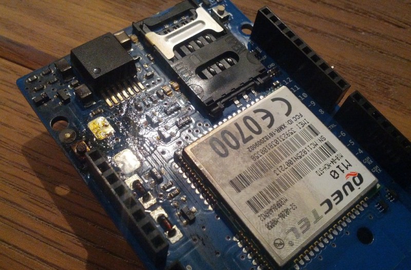
The value of the capacitor in question is 2,200uF. Part #592D228X96R3X2T20H, Mouser sells them for $3.50 each @ 500 minimum qty.
I’ve *never* seen a tantalum capacitor that big legitimately needed *anywhere*. Sure, you may need very low ESR to decouple certain fast transients. But when very high capacitance is also needed it’s usually done by pairing one or more smaller very low ESR caps, with a larger low ESR electrolytic to supply the bulk of the capacitance. I’m told this strategy is also superior in that it reduces ringing due to parasitic inductances.
But I could be wrong. So I downloaded the Quectel M10 GSM Module datasheet to see what it has to say about it:
“…a bypass capacitor of about 100 μF with low ESR is recommended. Multi-layer ceramic
chip (MLCC) capacitor can provide the best combination of low ESR and small size but may not be economical. A lower cost choice could be a 100 μF tantalum capacitor with low ESR.”
So Arduino went with the “lower cost” choice, which wasn’t lower cost at all – because they made it 22X larger than necessary! A MLCC with the recommended value is much cheaper than the part Arduino used, even if you choose a voltage rating higher than 6.3V for additional safety margin. And if you don’t, at least you don’t have to worry about fires if the margin is exceeded.
But I could be wrong about that too. And in fact, after also downloading the GSM Shield schematic, I discovered I *am* wrong. (I decided to leave my previous paragraph, which I completed before discovering my mistake, unedited as documentation of my process; mistakes and all.)
That massive tantalum cap isn’t on the supply pin for the GSM Module. It’s on the 5V side, serving as the input capacitance for a LMZ12002 “Simple Switcher” regulator. Ok, one more datasheet to download:
“Recommended minimum input capacitance is 10uF X7R ceramic with a voltage rating at least 25% higher than the maximum applied input voltage for the application.”
So, my final conclusion: They failed to meet the absolutely clear “25% higher” requirement, contributing to a hazardous situation. They used a tantalum where it probably wasn’t needed, and it certainly wasn’t at the datasheet’s recommendation. And although 10uF is a “recommended minimum”, a value of *220X higher* is plain crazy.
It makes me wonder if they just plugged some unrealistic numbers into TI’s design tool for the regulator, and used the results without questioning them. Or perhaps had some real-life issues with noise on the 5V rail on their prototype, and “solved” it by simply throwing bigger input caps at it until it worked; without investigating the real root of the issue. Plus generally failed to check their work better than a casual hobbyist posting on HAD, about circuits and components he had no foreknowledge of!
GSM modules are nasty in that they can draw up to 2 ampere peaks. With the Arduino usually powered using some ~500mA power supply, I can see why they would need the huge capacitor. The recommendation of 100 µF in the manufacturer datasheet probably assumes a li-ion battery with ample surge current capacity.
Another issue is that because there is no separation of the power rails, even if the GSM module could handle slight drops in the voltage when it is transmitting, the rest of the circuit might not.
If you require that the GSM module be powered off the Arduino shield, those 2A spikes severely constrain your choices. I don’t think the 2.2 mF tantalum is the right way to go, but it’s not the fundamentally stupid choice you think it is.
I think the right way to go is to put either a supercap or an onboard lipo. I don’t see any other options that don’t suck.
Since I’ve worked with this module in the past it would be interesting to know what document and version you looked at. The M10 hardware design manual that I have has these recommendations:
Recommended decoupling capacitors for limited current supply:
– Maximum current output of power supply: 1.5A
1500μF, <=0.045ohm ESR (e.g. VISHAY 592D158X06R3R2T20H)
– Maximum current output of power supply: 1.0A
2 x 2200μF, <=0.055ohm ESR (e.g. VISHAY 592D228X06R3X2T20H)
The max allowed sag is 400 mV for a 577μs long 2A burst every 4.615ms.
The capacitance is of course specified to sit at the 4.0V (nominal) battery net and not the input of the switching supply.
“M10 Hardware Design”, revision 2.0, dated 2010-07-30. It does in fact contain the information you provided, just a little further down from what I read. So I was wrong – again! Thank you. I enjoy being proved wrong when I learn something from it.
The LZM12002 switching regulator itself isn’t technically limited, as it can supply 2.0A max. But what feeds it, the regulator for the 5V rail, probably is limited.
So perhaps they decided to move the capacitance to the side where the limitation exists. And in doing so, neglected to increase the safety margin.
I wasn’t out to prove you wrong – I was just hoping that a newer version would have loosened the requirements since I can remember that those caps was expensive and annoying! Even though the recommendation was the same in the new version I at least got my document updated.
I was thinking that the the cap would have needed less de-rating if it would have been placed on the other side of the regulator, and they would also have gotten away with a regulator with lower current rating. Maybe such a large capacitance would interfere with the regulator if placed on the output.
IMHO a whole bunch of weird stuff came together in this case:
Wrong descriptions, as from the Arduino GSM Shield page (Power requirements): “The modem can pull up to 2A of current at peak usage, which can occur during data transmission. This current is provided through the large orange capacitor on the board’s surface.”.
Wrong part numbers in Arduino’s documentation (PCG0J222MCL1GS leads to ‘Nichicon Aluminum Organic Polymer Capacitors’)
If powering the GSM shield via VIN without an Arduino connected, U4 and U5 are left unpowered. Also, no caps on +3V3.
Trying to power a GSM shield from a 150mA source will not work. (5V reg on can shield: http://sigalabs.com/projects/vehicle-obd2-shield-with-stn1110-ic/). The LM317 on this shield will not provide more than ~700mA anyway, before the voltage drops.
And then there’s the tantalum cap.
I can’t really see how this could have not lead to trouble…
Nice review! I like your analysis of the schematic; even when you’re proven off again later. It does show how components and datasheets work together.
Ok, isn’t Tantalum mined by the FARC in Columbia, considered by the American government to be a terrorist organization?
My troll question is, “could these exploding Tantalum capacitors be a terrorist plot?”
That’s the real reason you have to run your gadgets through the x-ray at the airport, to scan for tiny tantalum bombs in your electronics.
No, it’s mined in the Congo by a panoply of thoroughly nasty organizations too diverse and numerous to name.
We all know what Sgt. Hartman said about the Congo too. That opinion still largely applies today.
Arduino: Designed for people that don’t know much about electronics, /by/ people that don’t know much about electronics.
This is hardly the first time tantalum caps tried to kill someone: https://en.wikipedia.org/wiki/Conflict_minerals
Hardly the first time tantalum caps have killed people: https://en.wikipedia.org/wiki/Conflict_minerals
That’s why I call them TANTRUM capacitors.
Never use CHEAP tantalum caps, use good ones and dimension them well. If in doubt, ask the manufacturer.
We are using tantalums in automotive electronics, where they have to withstand temperature shocks, vibration, temperatures from -40°C to +125°C, have to last 15 years, etc.
And automotive OEM’s are VERY concerned about potential fire and smoke hazards.
Is this GSM module really powered by 5V taken directly from Arduino power line? I am asking because most of contemporary GSM modules require voltage below that value. For example 4,5V is absolute maximum for popular SIM300D device.
Once I used old Motorola D15, which can take everything between 3V and 6V, but this device has own power circuit and I/O buffer for level adjustment.
I am using 6.3V tantalum caps in devices powered by li-pol rechargeable battery (4,2V max), I think it is quite safe margin of error. For decoupling GSM radio power I am using low-ESR electrolytic capacitors.
It’s one thing that they designed it with a wrong cap. Mistakes can happen, especcially when you have a lot of parts in a board. What does worry me is that they didn’t find out about the fire hazzard themselves. Don’t they test their products to the max before they start selling them?
Likely their test bed has a better power supply unit than many of their customers possess. Which would lead them to not replicating the worst case scenario.
Gulbransen organ used these by the hundreds per unit even for non needed cases. I just junked out a top of the line model from the 80’s when I turned on a pedal stop and red smoke wafted out of the stop tabs. It had other problems as well.
I’ve used quite a few tantalums in my time, and I’ve never had one go into meltdown or burst into flames. But I learned a very long time ago that caps should always be a at least a couple of times the rated voltage due to overshoot on the rail. Thats sort of the whole idea of caps, to smooth out voltage fluctuations due to fluctuating load current and or supply noise. And yes, reading the datasheet is very helpful, but also you must understand that sometimes there are caveats on datasheets and sometimes those are not so clearly explained or marked. A lot of the time, the schematics you see on datasheets were never intended for production or to be used other than for testing purposes or they may have actually never been built, they are simply there as “back of the napkin” calculations using “pure world” values that would fail to work in the “real world”. So buyer beware.
Remember it is ultimately the designer that is liable for choosing to
copy a “sample” schematic as is from a vendor without doing his/her
homework looking at whether or not the OTHER components not made by the
vendor in the schematic are specified correctly.
Those schematics are like those “suggested serving” pictures on the back
of a prepackaged “food” at the grocery store. They only showcase THEIR
product and really up to you and your skills to prepare it correctly.
In this particular case, the vendor of the capacitor Vishay stated very
clearly that the voltage derating values should be (50%) in an easy to read
table format on page 8.
A few places I have worked for used Tantalum caps almost exclusive for
products that requires high reliability and have not run into issues. We
had guild lines how to derate components correctly.
the capacitor derating guild
i KNEW you existed
I find it funny that people thingk they have an enginnering team that poured over capacitor specs. They picked one from the catalog and used it. They picked wrong.
“Makers” made it, the rest of us talk about how to fix it.
Now I am a little curious!
I just bought this shield:
https://dl.dropboxusercontent.com/u/56823168/20130925_152030.jpg
Can anyone tell me if this does have these “dangerous” capacitors, and if yes, are they rated so good for this item, that it should be okay to use without any danger, or are they too small?
Thank you very much
best regards
Joe
you’ll be fine. the yellow one is certainly too small for trouble
Thank you very much for your reply, now I’m a little more calm :-)
Isn’t red/orange a colour for warnings? :)
The two black ones 470(uF)/10V are Tantalum capacitors. Judging from
their location, they are replacement for the orange one. Newer/older design?
The rest of the orange part spec isn’t all that great as they optimize
it for its size and capacitance.
They picked the voltage rating. Can’t comment on the ESR or ripple
current rating as there are no proper part # to look up.
If they picked the right two caps, they could improve the ESR/ripple
current specs and actually make it safer. Less ESR means the cap see
less self heating.
Do you think I should be worried, or is all looking fine if you judge from the picture?
for more info see this: http://www.tinyosshop.com/index.php?route=product/product&path=65_118&product_id=464
thank you
How is that any DIFFERENT from the drop box one you already posted and I commented on?
BTW luke missed the black caps and that’s why I made my comment.
They are equal, it was just to give you some more information about the shield ;-)
As far as schematic style is concerned, the person drawing it is a
professional. This is something that matches what I do in my schematics,
I am biased, so I give it a 10/10. :)
It has none of the readability issues that most of the schematics
suffers from.
i.e. proper and liberal use of comments explaining the different parts
of the circuits, show the math of component values calculation, component
values are not blocked with tracks or other symbols, proper 3 point
joints.
As far as I am concerned, it is like coding style for the hardware. If
your schematic is sloppy drawn and can’t be bothered, chances are your
don’t care about minor details which _IS_ important as we found out.
Most of the fail ones falls into this group. This does not mean the
people that knows their stuff won’t be sloppy e.g. Sprites_tm.
People like bunnies, Elm-ChaN falls into the readable group.
The Arduino one has some bad readibility style although not as bad as
others I have seen.
I have not found any WTF in the actual schematic design. It is very
straight forward and easy to understand.
They use a Micrel LDO and use a 470uF cap for the input and outputs. The
derating values are reasonable. Not sure if it works, but I would guess
it should if the 5V is strong enough.
Still do not have a proper part# for the tant cap, so can’t comment. It
is made in China, so do run into risk of capacitor(s) of the day type of
quality issues.
First thank you very much for your detailed reply!
I know I have to use 5v 2A to deliver enough juice to the shield, so I guess the 5v should be strong enough. I am a little confused, is the tant cap. the orange one, or the blacks? – the orange one is labeled as follows:
“106C
21L32”
thank you
The black and the yellow ones are tantalum. Those are the typical
colours they come in. That part is just the molded case probably some
kind of epoxy. What’s inside that case is what counts.
The through hole leaded parts are epoxy dipped and they do come with
other colours too (like light blue, dark blue, green, orange, yellow). :)
See pictures: http://en.wikipedia.org/wiki/Tantalum_capacitor
106 probably means 10uF not sure about the rest of that code probably
case size code. i.e. packaging
In the schematic, it is labeled as /TA where TA probably
means TAntalum.
I think the ultra thin red one that caught fire probably only have a
conformal coating.
IMHO the Chinese knock off is a BETTER design all together. With the
well documented schematic, it is what Open Source design hardware SHOULD
have been.
Since the Radio part requires 4V or so which is generated from a 5V
source, you are looking at a 80% efficiency anyways even if you use a
linear regulator. You wouldn’t want a switcher without some additional
filtering. The Chinese design use a Micrel 3A LDO linear regulator
providing most of the current, probably not going to stress the tantalum
cap on ripple current and require ultra low ESR spec. Caps are already
derated correctly, so as long as they don’t use fake caps, you are
laughing.
On the datasheet graph (page 9), that LDO part can easily handle a 3A current
step with around 75mV droop using only a 100uF output cap. Actual design
has a 470uF output cap. It can meet the load requirement of the radio as
provided elsewhere in the discussion. Since the LDO drop out voltage is
0.37V (typ) and 0.6V (Max), as long as your 5V supply holds out, it
shouldn’t have any problems. i.e. Vin – 0.6V – 0.075V is higher than
4V-0.4V (allowable sag). So you are looking at the 5V supply not drop
below 4.275V under a transient load. That shouldn’t be too hard to meet.
There is a local 470uF cap at the input end for good measure. I would
say it is a good clean better design because it is cheaper and more
reliable.
The official design went out of the way just to try out some new and
more expensive parts for no obvious performance reasons. I wouldn’t
touch it with a 3 meters pole.
tekkieneet caught me there. in retrospect, missing 2/3 of the caps is a grand “duh!”.
however, IMHO these things are rather ok to use, as long as you run the whole setup through a sanity check, which the OP would have failed for sure.
tekkieneet:
As far as I can see Googling the orange tantalum cap. it is a 10uf 16v.
I will test the shield very careful and over long time, before running it for days.
It goes to show us all that we need to understand the equipment we’re using. We can’t just be hackers. We have to be engineers too. It also shows us that these companies that build electronics for the “maker” environment don’t always understand what they’re making. They are young companies with less experience. That being said, there are lots of dishwashers made by big companies that go on fire too. Maybe it’s a sign that the electronics industry is filled with people who don’t really understand electronics. Maybe these fancy degrees we have are not actually teaching us anything. Maybe we need to actually start teaching relevant information. Or maybe we just need to stop cutting corners to save a few cents.
Or maybe it was just a mistake.
Maybe!? Hah, I know first hand!!! And whats also scary; a lot of places don’t even use engineers or techs in the hiring process to vet out the new guys! They assemble a “hiring team” of people with no idea what a volt or ohm even is to “objectively” select new hires (whatever that means!?) !. It would be like your doctor needing to refer you to a neurosurgeon but having a plumber, a barber and a mechanic select one for you. So I’m not at all surprised when I find one of the new people without a clue to even the simplest of electronics concepts. People with actual degrees from some big name engineering schools a lot of the time.
So what about ‘wearable electronics’? Adafruit sell this a lot, and it’s kind of the opposite of doing good practice in ESD labs: sewing bare PCB’s to moving nylon… And then be amazed that it breaks down….
It is not like we are in the dark ages. There are tons of ESD protection
devices, and robust ways of designing circuits that can handle some abuse.
i.e. don’t just expose the raw I/O pins
If you put the PCB inside an ESD bag and provide proper ESD harden I/O
protections to the wires hanging out, I am sure you can stick it on a
long hair kitten that rolls around a house with glass, balloons and
nylon in dry winter.
They can SELL you more when that happens. So making a design mistake and
make the customer pays for it again. What a good business decision!
Tantalum capacitors do tend to fail dramatically if they’re put in backwards as well, and you won’t have to wait hours for it to happen ..
Im going to echo what everybody else here has said: Tantalum caps are great and extremely reliable when used properly. The key here is properly! They are more reliable than aluminum electrolytic caps because they are a solid dry dielectric that wont have PH problems or dry out over time like aluminum electrolytic types. They have VERY high energy density, which is why they fail so spectacularly. I have used and seen Tantalum caps used in many high reliability devices with very good results. Again, they just have to be used properly. It is not a very good design decision to use a 6.3v part on a 5v rail, and even more so a bad decision to use the 6.3v part on an anemic power supply, where the heavy current spikes WILL cause the cap to heat up because of ESR. Suppose the cap has only 1 ohm of ESR, and you pull 1.5 – 2A pretty regularly. The cap then has to dissipate approximately 4W of power every time that current is drawn! That is a lot! A 4w 1 ohm resistor is very large as far as components go, and it gets very hot, very quickly at its rating!
A side question, related only by that it involves manganese dioxide. It’s a long shot, but maybe someone here can help. Or suggest where I can best request it.
I attempted to replicate a CO2 generator from a patent description. Graphite electrodes were used to electrolytically break down a saturated solution of oxalic acid in distilled water, with a bit of magnanese dioxide added which was described as a “catalyst”. The first attempt worked perfectly, for two months straight, with gas production rate nicely controlled by current. No erosion of the electrodes occurred. The manganese appears to have plated out on one electrode, forming a semi-crystalline protective coating.
But all subsequent attempts failed. The manganese plating initially forms, then soon redissolves, leading to rapid electrode erosion.
hence why tanalums like the Vishay T96 series have a built in fuse… there is a price to pay though, less C*V per volume, but for many situations worth it.
Given their reputation, I wouldn’t be surprised at all if someone already used tantalum capacitors as explosive detonators to ignite handmade bombs.
I always wonder if anyone makes a tantalum or a electrolytic capacitor gun by discharging a high voltage caps through them.
Yes , I made type of gun using twenty 4700uF capacitors
Good to know, was just about to start building a gizmo with that shield. Will swap that part. Wouldn’t want clients spamming support messages about the terminal exploding in their faces.
You may need arduino SIM900 Quad-band GSM/GPRS module here: http://www.elecfreaks.com/store/gprsgsm-moduleefcom-pro-efcompro-p-450.html
what is the gsm arduino voltage?