
One of the best things about DIY synth building is that you can create devices that just don’t exist in the commercial marketplace. In this session, we’ll build a looper / sequencer the likes of which you may have never seen. And it’s groovy. Today we’ll also get back a little closer to the soul of the series. In this session, nothing is analog — this is pure Logic Noise.
The shift register is the centerpiece chip this session, and a great device in its own right. We’ve got a lot of ground to cover, so watch the teaser video and then let’s get going.
4015 Dual Shift Register
Shift registers are most commonly used as serial-to-parallel or parallel-to-serial converters. That is, they either take in a bunch of bits singly and then output them all at once, or they take in a bunch of bits all at once and then spit them out one by one. The 4015 is a (bit obscure) member of the former group.
Inside a shift register are a bunch of one-bit memory cells implemented as type D flip-flops. Each cell stores its input value when it receives a clock signal. What makes it a shift register is that the cells are arranged in a line, with a typical cell’s input hooked up to the output of the cell before it. When the clock pulses, the value in the first cell is transferred to the second, which transfers its value to the third, etc.
Think of a bucket brigade — a line of people passing buckets in one direction. Here, whether the buckets are full or not represents a logic state. After four buckets have been passed into the line, for instance, we could tell everyone to stop and look at the contents of their buckets. That’s a simple 4-bit serial-to-parallel shift register.
The 4015 has two completely independent 4-bit shift registers inside. There are a lot of different serial-to-parallel shift register chips out there, each with subtle differences, but it’s the fact that you get two registers in one chip that makes it a nice choice for Logic Noise applications. And, as we’ll see soon, with a little wiring you can easily convert it into a single 8-stage register.
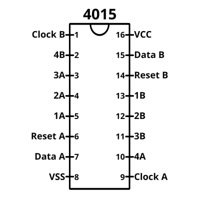
To use this chip, you connect up power and ground. Pull the “Reset” lines low to enable a register. Say we’re using the A register. Then, on the next positive-going Clock A transition, whatever logic voltage was present on the Data A input gets shifted in and shows up on the 1A output. Whatever value was on 1A gets shifted to 2A, and so on. The value that was on 4A disappears.
One caveat with this chip is that the clock line is picky — it wants nice clean clock transitions. If you’re trying to clock the chip with a dodgy signal, you can use our 40106 inverter with Schmitt trigger for its actual intended purpose (for once) and pass the signal through one inverter stage to get a nice clean clock out of almost any voltage input. That’s not our problem here, though, because we’re using the 40106 as our clock source to begin with.
The other caveat is more applicable, and you’ll see examples throughout the demo videos. The 4015 data and clock lines have very sensitive inputs and love to pick up stray signals. So when you unplug a wire, you’ll often hear crazy noises that are a product of driving the line with your power line frequency (50Hz in Europe, 60Hz in the USA).
The solution is to make sure that you’ve always got a defined voltage on the pin. If you’re going to be doing live-patching, this can be as simple as adding a 100k resistor to ground for any pin you’d like to default low. Most anything you connect will be able to lift the line up, but when you let it dangle it’ll come back down to ground.
Shift Register as Pattern Generator
OK, but why are we talking shift registers here? As you’ve hopefully seen in the teaser video: because they can be used as sequencer-like pattern generators and digital loopers. (And more!)
First, let’s hook up one side of the 4015 and trigger our drum and cymbal circuit with it. We got lazy and only built up three oscillators from the cymbal circuit, so it’s kind-of a cymbal / snare hybrid. We’re going with “snymbal”.
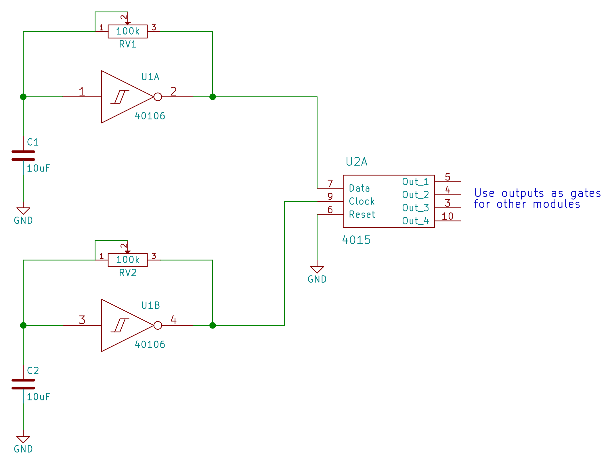
Any one of the four output taps from the shift register can serve as our gate source for the drum or snymbal. But we’ll take the traditional route and attach the bass to output 1A and the snymbal to 3A. (You could double the 3A pulse to the bass drum with a diode OR as we did last session if you really wanted the four-on-the-floor dance beat.)
Now all that’s missing is a clock and data source. A 40106 oscillator with a 10uF capacitor makes a good clock, and in the video we have a bunch of fun by putting another similar oscillator into the data line and de-tuning the two clocks from each other to make some longer rhythmic variations.
The circuit is as simple as the above description. Playing around with it is well worth your time.
Now if the patterns available in four bits aren’t enough for you, it’s time to connect up the second half of the chip. Because the chip has two independent shift registers, you could simply connect up more clock and data oscillators and away you go. Getting something that sounds good is then a matter of carefully adjusting the clocks to sync up with each other just right. Most people just copy the Clock A line over to Clock B.
If you want to create crazy polyrhythms, you can use the output from a 4017 counter to provide the second clock source. Copy the first register’s clock to the 4017’s input, connect the reset line to the desired rhythmic division, and use any convenient 4017 output (say, Q0 because it always pulses) as the second clock.
But for our purposes, things will get interesting enough soon. So after a little experimentation, we’ll take the most boring option and configure the 4015 as a single 8-bit shift register. To do this, simply connect both clock inputs to the same clock source and connect output 4A to the input Data B. That way, when a bit has worked its way through register A, it’s straight off on its way to register B.
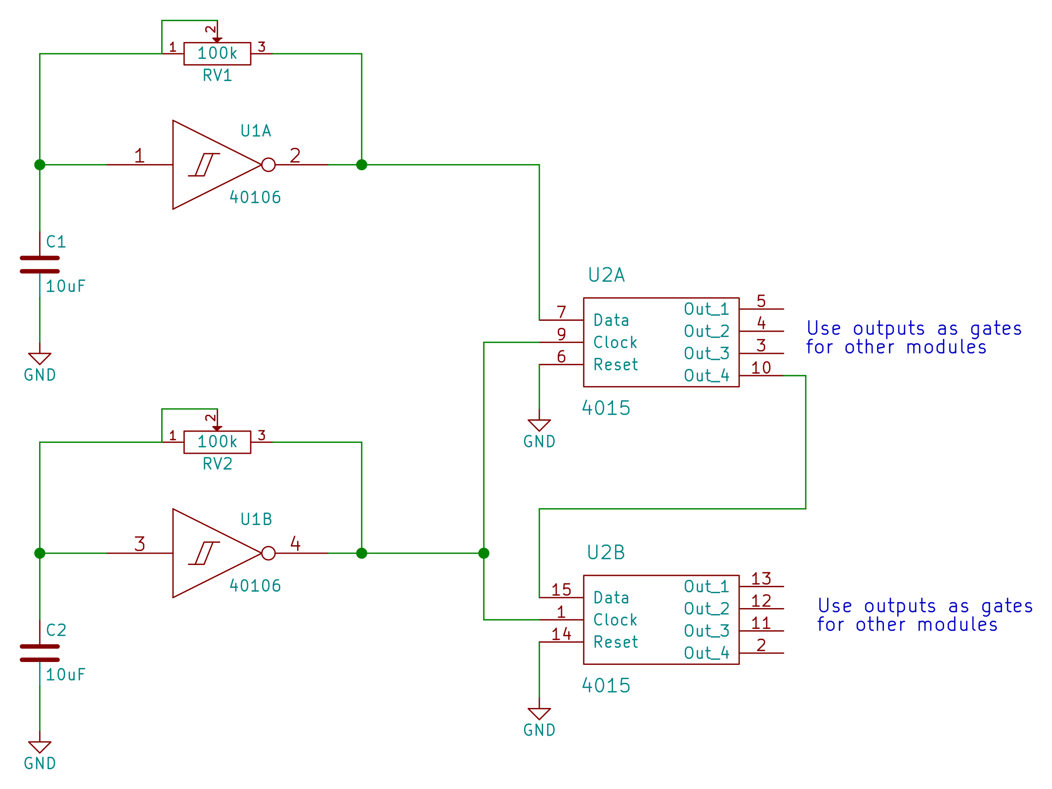
Again, the logic of all this is very simple. What’s interesting is the way a shift register creates a stream of pulses that are rhythmically delayed from each other. You just have to hook it up to some sound sources, play around for a while, and you’ll see what we mean. Don’t forget to change up the output taps to see how it changes the resulting patterns.
At some point, you’re going to wish you had more control over the patterns shifting through the registers, and one way is to take over the Data inputs yourself as we did in the video. As mentioned above, these chips are very sensitive to stray signals, so you’re going to need to connect pull-down or pull-up resistors to the data lines to prevent them from taking on variable values when the pushbuttons aren’t pressed.
And soon after that, you’re going to hate having to press the button so often. Wouldn’t it be great if you could set up a pattern and have it simply repeat? The Logic Noise equivalent of a loop sequencer, or something? That’s exactly where we’re headed.
Shift Register as Looper
Making a pattern loop through a shift register is painfully simple. Just connect the last (or whichever) output back into the input data pin to make a data feedback loop. For eight steps, that’s 4B into Data A. For bizarre tempos, you can do whatever you like. Heck, you can even automate this return through a 4051 switch chip and select the number of steps externally. (Foreshadowing!)
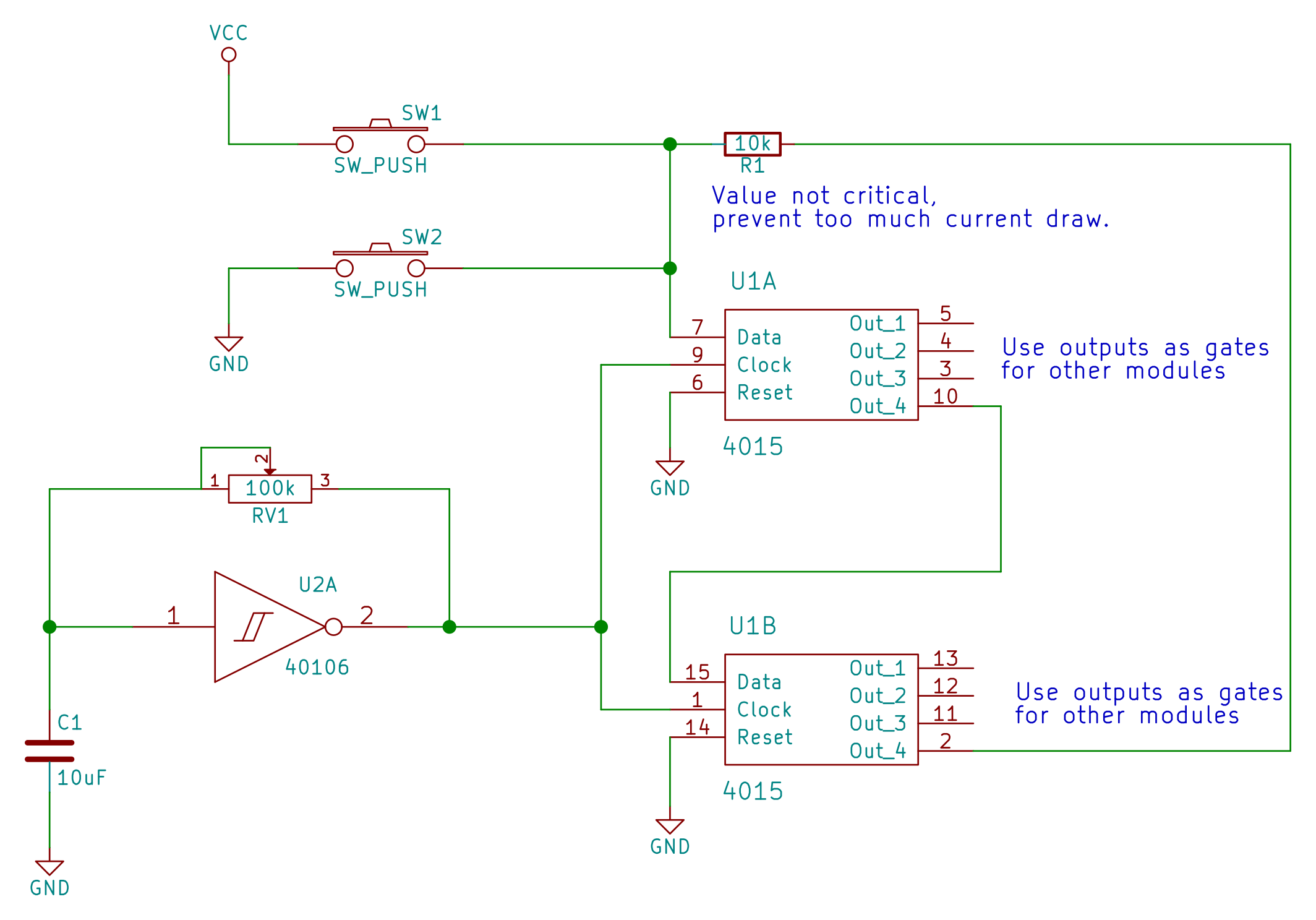 A loop isn’t any fun unless we can insert and remove pulses from it. And conversely, it’s a real hoot once we can. Simply connecting pushbuttons into the data feedback won’t quite work. If you try to ground the data line while the 4015 is trying to drive it high, for instance, you’ll end up drawing too much current from the chip and it’ll glitch out. The solution is to insert a resistor into the feedback loop and connect up your pushbuttons on the Data A side of things.
As with all the examples this session, the circuit is dead simple. We’ve dropped the old Data oscillator, connected output 4B to Data A through a medium-sized resistor (10k should work great), and hooked up pushbuttons to ground and VCC. Almost no pain, tremendous gain.
Looping Oscillators
If you’ve been following along with Logic Noise, you’re already thinking of how to drive oscillators with this shift-register looping sequencer. Indeed, it’s so easy that we did it in the first session. The humble diode gate circuit that we used to create a sync oscillator does just the trick.
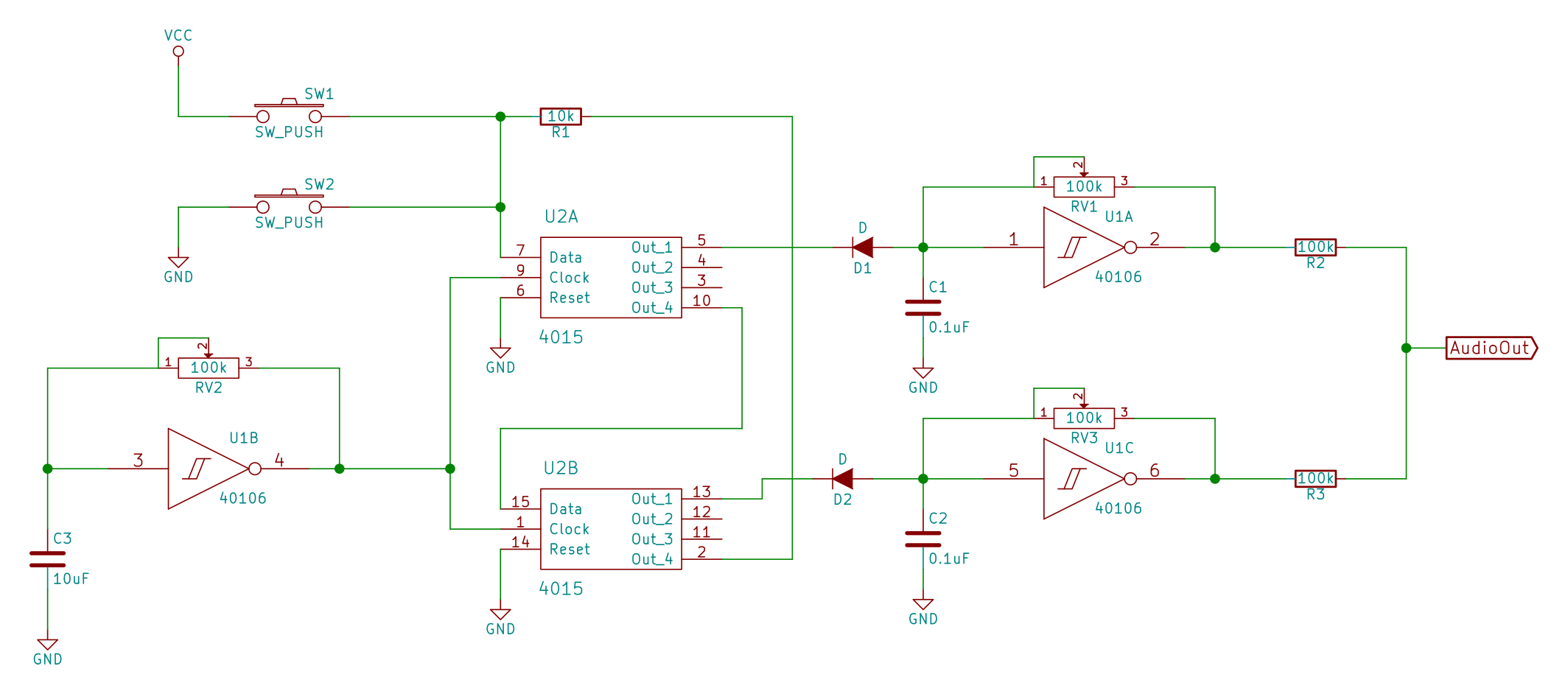
For instance, when the shift-register’s first output is low, the diode D1 pulls down the oscillator’s timing capacitor (C1) and prevents it from charging up through the variable feedback resistor (RV1).
I’ve summed the oscillators’ outputs together with 100k resistors. Feel free to change the values here if you want one oscillator louder than the others. And feel free to use as many oscillators as you’d like notes or voices.
But do note that it gets cacophonous (or at least polyphonic) pretty darn fast. The difference between a shift-register sequencer and a “normal” sequencer is that you can insert multiple pulses into the shift register. For each pulse, you’ll play the pattern corresponding to the connected oscillators. Even with a small number of pulses circulating, you’d better tune up your oscillators to play nice with each other, because they’ll probably all be sounding together at some time.
The other drawback with this straightforward approach is that it’s simply a lot of wires to hook up. If you want to play eight notes, you need to build up eight individual synced oscillators. So let’s take a minute to build up a pitch generator that plays nice with our shift register looper.
The Melody Generator Aside
As far as I know, this circuit is the invention of folks in the Electro-Music Lunetta forum, but I’m sure it’s older still in some variant. It’s simple and brilliant and creates (mostly) harmonically related pitches with just two chips. It’s easily worth a diversion.
Last session, we used the 4017 counter chip to build a “normal” sequencer that puts out one pulse on each output once per cycle, and does so in order. We also discussed that you can change the length of the sequences by connecting the Reset pin to one of the counter’s outputs to restart the count before the tenth beat.
At its heart, the Melody Generator is just a 4017 counter running at audio frequencies. If we used an audio signal as input to the 4017, with the Reset line grounded, we’d get out a pitch that’s 1/10th of the input. Changing the count by connecting the reset pin to other 4017 outputs gives us other divisions of the input pitch. So far, so good.
Next, we automate the connection of the Reset line by using one of the more versatile chips, the 4051 8-way switch. This means that the 4051’s three select lines control which of the 4017’s outputs triggers its own reset, and thus the select lines control the resulting divided output pitch.


The circuit is fairly simple, but you’ll have to be a little careful connecting up all of the lines if you’d like predictable results; the pins are in “random” order on both chips. Also note that we’re skipping the first two 4017 outputs, and using the first as our output. You want to hook up the 4017’s Q2 to the 4051’s X0 and so on. Here’s a cheat sheet to help.
You must build this circuit. You’ve got the 4017 from last session and the 4051 from a few sessions ago. You have no excuse.
Melody Generator Looper
The beauty of the Melody Generator circuit is that you can think of it as a black box. Feed in an audio-rate logic waveform and a three-bit binary signal, and you get out corresponding divided-down pitches. We can build up the oscillator in our sleep by now, but what about the remaining three logic signals?
If you like complete chaos, you could feed tempo-rate clock signals into the three 4051 inputs. The relative tempos of the oscillators make patterns that change over time depending on how close the oscillators are to being integer multiples of each other. Hard to control, but a freak-out in the good sense of the word.
 If you like complete order, think back to the way we originally drove the 4051, with a 4040 binary counter. Simply clock the 4040 with a tempo oscillator and you’ll run through all eight notes that the Melody Generator produces. Connecting the taps up in the wrong order can make interesting patterns.
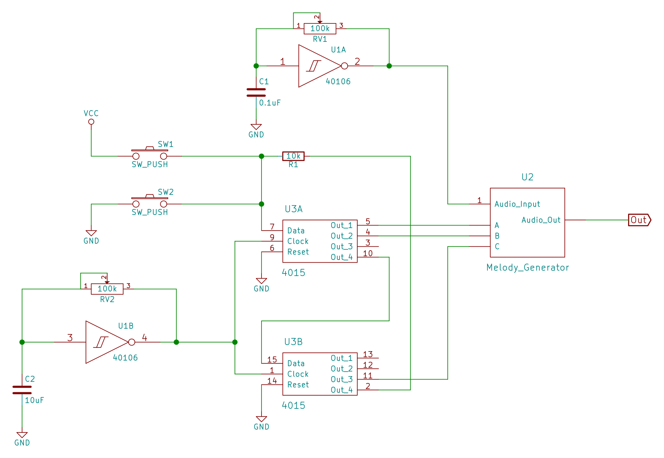
Somewhere in the sweet spot between chaos and order lies this session’s masterpiece circuit: the Melody Generator Looper. All you have to do is hook up the three Melody Generator logic inputs to three different output taps from the looper.
Now be prepared to spend an hour or more exploring what this circuit will do. Add and remove pulses from the cycle, move the taps around, and experiment with how it all interacts with the percussion elements we’ve already built in.
Indeed, what makes this circuit weirdly satisfying is that it lies on the edge of controllability and chaos. When you introduce a pulse into the cycle, it changes the pitch of the Melody Generator’s notes, but it changes the rhythm of whatever you’ve attached as percussion. Only changing the taps around by manually re-wiring the circuit changes the rhythm of the melody. One extra pulse in circulation changes many notes. Somehow, though, it all seems to hang together musically.
Melody Generator Looper Royale with Cheese
So you want fries with that? How can we tweak this circuit to get even more out of it? Well, we’re glad you asked. Here are two simple tweaks that’ll make a real difference.
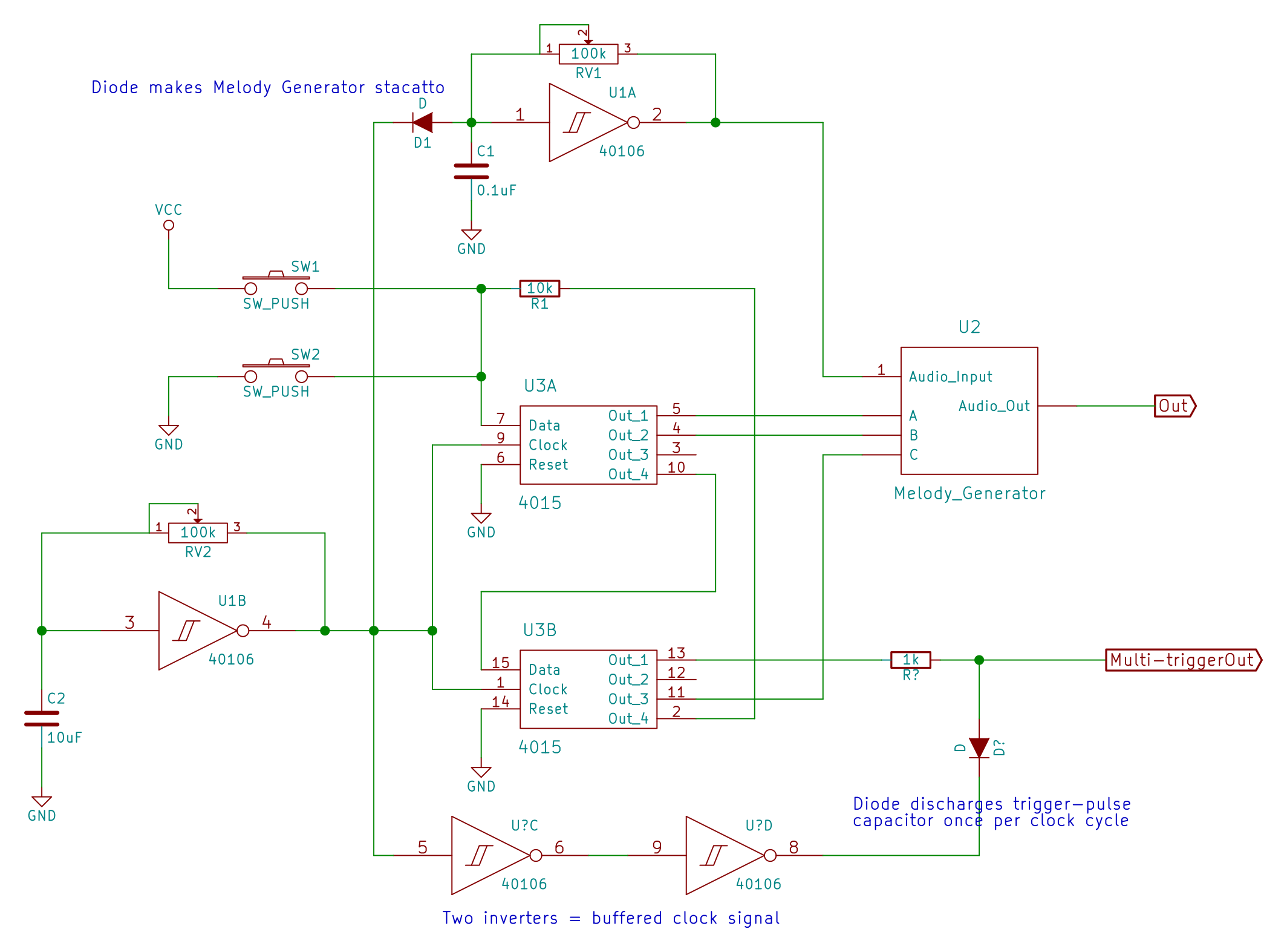
The first tweak makes the Melody Generator play staccato notes instead of running each note into the next one. It’s the same old gated-oscillator trick all over again, honestly. Just connect up a diode to the capacitor in the audio oscillator that feeds into the Melody Generator, and run the other end down to the looper’s tempo clock.
Now you may have noticed that if you use something like our Twin-T bass drum in this circuit that it doesn’t re-trigger with each new pulse. That is, if you have three pulses in a row, the bass fires once and then not again until after there’s a gap. This is a side-effect of the way that the gate-to-trigger pulse circuit is built. We can work around this.
The cause of the single triggering behavior is that we’re using a capacitor to turn the rising edge of our square wave pulse into a short spike. If the looper-side of the capacitor cannot discharge before the next pulse signal, it doesn’t generate the spike and the drum doesn’t sound again.
The solution is just the same as with the staccato modification; use the tempo clock oscillator to pull the capacitor down halfway through the pulse. But in the case of the cymbal or bass drum interface circuits from last session, they draw a significant amount of current, probably enough to swamp the clock oscillator. So the full solution is to buffer the clock circuit with another stage on the 40106, but in practice you’ll need two stages because you want an actual copy of the clock and not an opposite-polarity copy (though the opposite-phase version makes a nice additional beat, as discovered by mistake in making the video).
Extensions
There’s so much more to do with this looper circuit. First, you could want to insert pauses where the Melody Generator doesn’t play any note. We connected the 4017’s Inhibit line to ground, but if you tie it low with a pull-down resistor you can silence the Melody Generator by sending it a logic high voltage. How to sequence this is left as a challenge to the reader. Driving it with an audio-frequency oscillator, on the other hand, produces something reminiscent of our XOR circuits.
Of course you could chain two 4015’s together to make a 16-step looper. Or more, if you’ve got the breadboard space. On the other hand, there are other shift register chips with longer sequences out there. Just be sure that you’re getting one with enough parallel outputs to be useful. For instance, the 4031 has a 64-step shift register, but only the last step is exposed (that said, you can make an awesome one-bit looper with that chip). Something bizarre like the now-discontinued 4006 would be fun if you can find one. The 4094 gets you eight stages and has some nice extras.
Finally, you can add in a 4070 XOR and make a linear-feedback shift register (LFSR) which is often used as a quick-and-dirty pseudo-random number generator. To make a maximum-length LFSR with our setup, connect taps 4A, 1B, 3B, and 4B back into Data A through cascade XORs. LFSRs aren’t so musically useful that we’re writing them up, but they’re still cool. Picking non-standard taps for your LFSR will create cycles with shorter periods, though, which are worse for random numbers but significantly better for musical applications.
Or use one 4-step shift register for the Melody Generator and the other to choose taps off of a 4040 binary divider for octavey arpeggios. It’s another level of complication, but it’s awesome. You’ll find two late-night YouTube videos here and here.
Next Session
We’re not done with Logic Noise by any stretch of the imagination, but with the end of this session, we’ve rounded out a body of tricks with digital logic chips (and their abuse to create analog waveforms) that’ll give you more than enough rope to hang yourself and some of your neighbors. If this were a college curriculum, we’ve just finished Logic Noise 101.
So next session we’ll take stock of where we’ve gotten so far, and start thinking about building up discrete circuits and how to interconnect them. We’ve had requests for a Bill of Materials (or shopping list?) for the series, and that makes sense just about now, because it’s time to build yourself a stand-alone Logic Noise synthesizer.
We’ll also include a literature review of sorts — links to further reading, projects, and directions to build on what we’ve done so far. In short, tying up all the loose ends that have come up along the way.
But Logic Noise 101 coming to an end also means that we’ll start up on Logic Noise 102 fairly soon. And the central topic is going to be one that we’ve studiously avoided so far: voltage control. Stay tuned for a whole new can of worms.


why could this all not be one video?
Why cant you keep your mouth shut?
How do you tell if someone’s mouth is open over the internet?
THIS… is why I read HAD! Fantastic.
Great news about Logic Noise 102. Should we expect some delay between 101 and 102, or are you planning to continue smoothly?
Summer vacation? I hope not! ;-)
Smoothly, smoothly! (I’m having too much fun with these.)
I just want to take one week off to do a background-reading, loose-end-tying up issue, then it’s right on to trying some really hacky stuff to get voltage control to work with these chips.
Sorry if I was confusing.
Really enjoyed the series so far and I’m looking forward to the upcoming stuff.
Maybe I’ve missed it in one of the previous parts but I was wondering about the circuit you are using to grab the audio output with your computers sound card.
Could you share a schematic? (Or perhaps someone else can)
So far I’ve played around with a speaker but it would be nice to bring the signal to line input levels and record it. I have not dared play yet out of fear of copious amounts of blue smoke escaping my pc.
Re: blue smoke. Reasonable, but probably not a problem. The voltage levels that these logic chips put out is waaaay too hot for your line in, for sure, so you’ll end up with a bunch of distortion. But I doubt you’d smoke anything, esp if you’re only powering with 5V instead of 12V. Anyway, doing it right is easy enough, and I’ll be covering a mixer/output next session.
But if you can’t wait, the short version goes like this:
logic out -> big capacitor (47uF? 100uF?) -> 10k resistor -> 100k potentiometer set up as voltage divider with the output off the center tap and ground to your input.
Basically, a big cap filters out the residual DC voltage without cutting out the bass. The 10k resistor is for safety, and the 100k pot drops the voltage down. Aim for 1V peak-to-peak on the output with a full-volume square wave and you’ll be safe.
With a 4069UB (unity-gain buffer) driving the cap/potentiometer output circuit, it also works for headphones. Get yourself a stereo jack, or just clip on to the phones with crocodile clips and you’re set.
Many thanks Elliot. You have done an excellent work with these posts.
Great work! On my next Mouser order I am planning on picking up a handful of logic chips to play around with this stuff myself.
Thank you for the excellent series!
I’m putting together a shopping list for next time if you’re patient (or lazy). If you’re impatient or a go-getter, pick up a couple 4046 PLLs as well so that you’re good for the next-next session.
Glad you’re enjoying! It’s a bottomless rabbit hole of chip abuse and fun, as far as I’m concerned.
This may have been answered in one of the earlier posts, but will 7400 series logic work the same way as the 4000 series logic chips that are being used in a lot of these posts?
Yes, they do. keep in mind however that they work differently. For starters, TTL logic gates are mostly current sinks compared to CMOS ones that are current sources, i.e. you have to add pullup resistors at TTL gates outputs and take into account the power supply limits. CMOS oscillators compared to TTLones allow you to play with power supply to obtain different frequencies. Of course the two technologies can be mixed but care must be taken not to overload CMOS gates outputs with TTL gates inputs. Data sheets are a must read, search for Fan-In/Out values.
Also sounds could be slightly different due to the different technology.
What qwerty said. :)
I’ve done a very similar workshop with the 74HC family of chips, and the only real difference is that you gotta keep the voltages around 5V, which means 4xAA cells instead of a 9V battery. Which sounds trivial, but not having to worry about whatever you’re plugging into (with the 4000’s) is a real convenience, and is the sole reason I’m not doing 74HC logic with this one.
Quick correspondance off the top of my head, and from the bottom of my kit box:
40106 -> 74HC14
4069UB -> 74HCU04 (where the U is important)
4070 XOR -> 74HC86
4040 Counter (not exactly the same?) -> 74HC193
4051 -> 74HC4051 (no, really.)
and for shift registers, I was using 74HC164s which are straight 8-bitters rather than a dual 4.
(Wow, I think that’s a pretty complete list — I think I’m a big nerd.)
Again, what qwerty said: some differences with schmitt trigger thresholds = different frequencies. But we’re tuning everything up by hand anyway. Meh.
In short, go ahead if those are the chips you’ve got on hand.
I forgot to mention two must read books for anyone wanting to experiment with these devices: the TTL coookbook and the CMOS cookbook, both by Don Lancaster.
I only wish that the CMOS Cookbook had more (and more modern) chips in it.
But for what it has, it’s fantastic. It’s on my desk.
4040 Counter -> 74HC4040
also 74HC4020, 74HC4060 ripple counters
Excellent goods from you, man. I’ve understand your stuff previous to and you’re just too magnificent. I actually like what you’ve acquired here, certainly like what you’re saying and the way in which you say it. You make it entertaining and you still care for to keep it smart. I cant wait to read far more from you. This is actually a terrific web site.
How about schematic of this whole series posted somewhere for download?
thanks!
Followup?
Great, has renewed my desire to build a Lunetta synth / noise box type thing.gas