
So far on Logic Noise, we’ve built up a bunch of sound-making voices and played around with sequencing them. The few times that we’ve combined voices together, we’ve done so using the simplest possible passive mixer — a bunch of resistors. And while that can work, we’ve mostly just gotten lucky. In this session, we’ll take our system’s output a little bit more seriously and build up an active mixer and simple stereo headphone driver circuit.
For this, we’ll need some kind of amplification, and our old friend, the 4069UB, will be doing all of the heavy lifting. Honestly, this week’s circuitry is just an elaboration of the buffer amplifiers and variable overdrive circuits we looked at before. To keep things interesting we’ll explore ping-pong stereo effects, and eventually (of course) put the panning under logic-level control, which is ridiculous and mostly a pretext to introduce another useful switch IC, the 4066 quad switch.
At the very end of the article is a parts list for essentially everything we’ve done so far. If you’ve been following along and just want to make a one-time order from an electronics supply house, check it out.
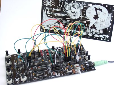 If you’re wondering why the delay in putting out this issue of Logic Noise, it’s partly because I’ve built up a PCB that incorporates essentially everything we’ve done so far into a powerhouse of a quasi-modular Logic Noise demo — The Klangorium. The idea was to take the material from each Logic Noise column so far and build out the board that makes experimenting with each one easy.
Everything’s open and documented, and it’s essentially modular so you can feel free to take as much or as little out of the project as you’d like. Maybe you’d like to hard-wire the cymbal circuit, or maybe you’d like to swap some of the parts around. Copy ours or build your own. If you do, let us know!
OK, enough intro babble, let’s dig in.
DC Bias Voltage
We perceive compression waves in the air as sound when they reach our ears. We make these compressions by pushing and pulling a speaker cone back and forth. And to make the cone move, we need to get current to flow one way and then the other through the speaker’s magnet windings.
Why the return to fundamentals? Because it’s important to think of the voltages and currents that we want to amplify as being bi-polar, oscillating around some central voltage level. When the signal voltage is higher than neutral, current flows one way and the cone gets pushed. When the signal is lower, current flows the other way and the cone is pulled. The neutral voltage around which we’ll oscillate is called a DC bias (or level) voltage.
In the course of Logic Noise we’ve ignored DC bias voltage whenever possible, but in mixing several signals together, we can’t do that anymore, because signals only add up correctly if they’re generated with respect to the same bias voltage.
 We’ve gotten away without blocking DC voltages before because our square wave and triangle wave signals were biased around VCC/2, just like an amplifier with feedback built from a 4069UB inverter is. It all worked fine until we introduced the drum and cymbals circuits, which are so strange that they don’t really even have a well-defined DC level.
Blocking DC voltage is simply done by passing the signal through a capacitor. How large? Large enough that combined with the input resistance of the next stage in the audio chain, it doesn’t cut too much into our low frequency components. In the case of the 4069UB output amplifier stage, a 1 microfarad capacitor will do nicely.
So for now, let’s assume that we first pull the DC level off of any signals that we’d like to mix together, noting that we can “get away with it” for full-swing square waves. Now it’s time to get down to the mixing.
Mixers: Passive and Active
Passive Mixers
 “Passive mixer” is a two-dollar name for combining signals together by passing them through resistors. The higher the resistor value, all other things equal, the quieter the contribution to the overall mix.
It’s the simplest way to add a few signals together, and you should play around with passive mixing anyway, just to get the feel for it. The key to making a passive mixer work is using relatively large resistors for all of the mix inputs.
The downside of the simple passive mixer is that because all of the signals combine at the junction, one signal can influence the others. Essentially, each input signal can pull the junction’s voltage higher or lower than the neutral voltage, and this can feed back out to the other “inputs” through their input resistor. Passive resistor mixers are tremendously simple, but they don’t isolate the signal sources well from each other.
Active Mixers
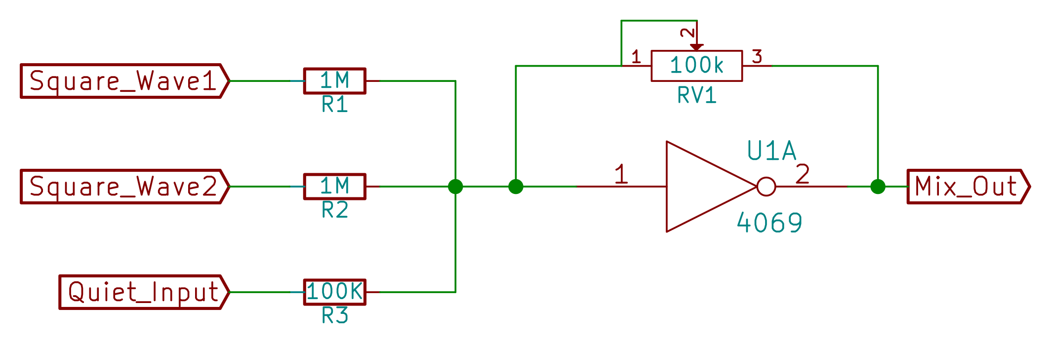
The trick to active mixing is adding negative feedback. Otherwise, it’s just the same circuit as the passive mixer, but it’s a whole lot better.
 Remember from the session on filters that the inverter acts as if it were trying to zero out any net incoming signal current that shows up on the input pin; the logic is that if the voltage on the input rises up above the switching point, the output goes low and fights it back down again through the feedback path.
How much resistance is present in the feedback determines how hard the inverter needs to work to cancel out the input signal. More feedback resistance leads to larger voltage swings on the inverter’s output, which end up as louder tones in our headphones, so the feedback path is a great place to add in a master volume control knob.
In the passive mixer example, when one input was high, it raised the voltage at the junction which could then flow “backwards” to the other connected circuits through their input resistors. In an active mixer, when one input is high the inverter cancels it out by lowering the overall mixed output voltage until the input to the inverter sits at its neutral point again. By the negative feedback mechanism, the junction of all the summing resistors is held at a constant midpoint voltage, and none of the inputs can affect each other. Only the output voltage swings around.
Here we see the need to remove the DC level from the input signals — the 4069UB will do whatever it can to hold its input at roughly VCC/2 by pushing current through the feedback loop. A 1uF capacitor before each input resistor will take care of that.
Beyond isolating the inputs from one another, we can also control the gain of an active mixer by changing the value of the feedback resistor. This gives us a simple place to insert a master volume control just by replacing the feedback resistor with a potentiometer. The convenience of a master volume knob should not be underestimated.
If you’re mixing signals, and you have electricity at your disposal, you almost always want an active mixer.
Multiple Input Volumes
The main function of a mixer is to make a bunch of sounds with different volume levels play nicely together. For instance, the square wave output of a 40106 oscillator swings fully from GND to VCC, while the (unbuffered) triangle wave coming from the input of the same oscillator is a lot quieter. The bass drum circuit is also by nature fairly quiet, and the output of the VCA that gave the cymbal its percussive envelope swing only a few volts. Aesthetically, you’ll want to tweak the volume of each different sound source.
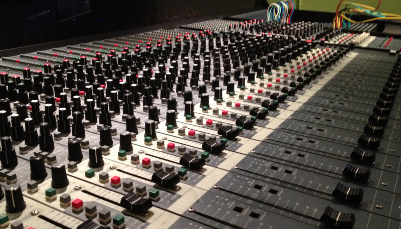 A studio’s mixing console is dominated by an impressive array of faders that fine-tune the volumes of the individual tracks. But before we end up investing in hundreds of dollars of fancy potentiometers, let’s see how far we can get with a bunch of one-cent resistors.
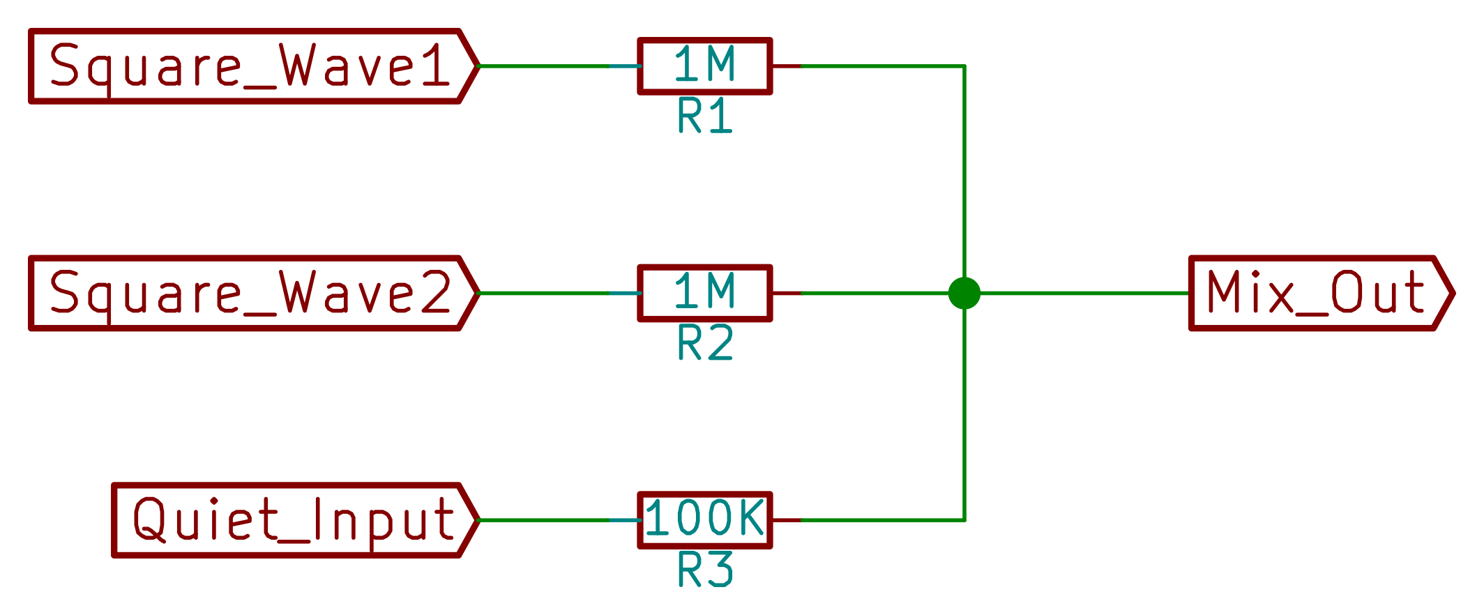
Let’s think about this like an engineer for a second. We want around one volt peak-to-peak of output signal, either for line-level inputs or for headphones. That means that if we’re seeing 9V peak-to-peak square waves, we’ll want to cut them down by about a factor of ten. On the other hand, the one or two volts peak-to-peak that we get out of the low-level signals can plausibly be run through with simple unity-gain buffering. (Bear in mind, this is all before the global output volume control knob.)
If we’re using a 100k potentiometer for the variable feedback resistance (and overall volume), this means that we can use something around 1M Ohm for the high-volume digital signals to knock the amplitude down by at least a factor of ten. Using a 100k Ohm resistor for the quieter signals means that they’ll pass through with unity gain when the channel’s volume knob is turned up to maximum. Of course, you can tweak these values to fit your exact preferences by picking different resistor values.
So round up a bunch of noise-making devices and pick some input resistor values that make them sound good together. (Remembering to remove the DC level with a capacitor if necessary.) If the end result works, nobody will know that you didn’t spend hundreds or thousands on a mixing board.
Headphone Out and Line Out
We saw DC bias issues on the input side, and DC bias raises its ugly head again on the output. Our amplifier’s output is centered around VCC/2, but for headphones (or other speakers) we ideally want no current to flow at this neutral voltage level. This suggests two solutions. First is to create a constant “virtual ground” voltage level at VCC/2 and feed the headphones with our signal and the virtual ground. The other is to strip the DC bias off of the signal and connect the downstream headphones or amplifier to real ground.
Virtual Ground
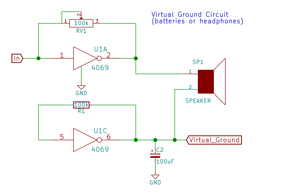 The clever way to create a virtual ground at the 4069UB’s neutral voltage (roughly VCC/2) is to set up an inverter with negative feedback as usual but with no input signal. The output of this inverter will be constant and exactly at the inverter’s switching midpoint, so we can use this voltage as the symmetric voltage midpoint that we need for the headphone’s “ground” connection. In the circuit here, a big (100uF) capacitor keeps the VCC/2 level steady. If you’re only going to be driving headphones, or if you’ll only be running the circuit on batteries, this is the hi-fi way to go.
The virtual ground solution runs into trouble when our circuit and the amplifier share a ground connection, as can happen when both are powered by (switching) AC adapters. Then the output’s virtual ground (around VCC/2, remember) gets connected directly to actual ground, and that’s not good. The 4069UB will struggle trying to pump out VCC/2 into a short to ground, probably get hot, and certainly not work so well. The moral of the story: if you use a virtual ground voltage, don’t connect it to actual ground.
Output Capacitors
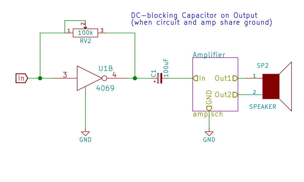 If you might have this shared-ground situation, the simple solution is to include DC-blocking capacitors on the output for each of the two stereo channels. While it was easy enough to just say “1uF capacitors” on the input side, the size of output caps should probably be larger but this depends on the load resistance and the amount of current we’ll need to drive into the load.
For example, I have a pair of headphones with 32 Ohm drivers inside, which puts the cutoff frequency of a 100uF capacitor at 1/(2*pi*C*R) = 1/(2*pi*100uF*32 Ohms) = 50 Hz — a low pitch, but one I’d like to hear. Maybe 220uF would be better for low impedance headphones. On the other hand, a less-demanding pair of 600 Ohm headphones will run fine with a 100uF cap down to around 3 Hz which is way below human hearing, and more like a fast tempo than a low note. You could probably get away with 10uF in this case.
In sum, the capacitor-based solution won’t end up shorting to ground, but requires a fairly big capacitor to pass bass notes. The virtual ground solution is clever and works perfectly well with headphones or when battery powered. Shorting the virtual ground to actual ground is to be avoided.
(Discrete) Stereo Mix
Stereo audio is nothing more than a right and left channel, that is two inverters on the 4069UB instead of one, but it’s a great step forward for our synth devices. You can either send all of one instrument voice to the left or right channel, or connect a single voice to both channels through different input resistors.
 It’s nice to have a simple stereo jack breakout board at this point — something you can simply clip or plug into your circuit and then connect up to your headphones or amplifier. Ours was made by soldering a 3.5mm stereo jack to a scrap of copper-clad, traces hand-drawn with a Sharpie, and etched. We tossed on some small wire loops to serve as nice ‘scope test points, because it’s nice to see as well as hear what’s going on.
Let’s take a break from all this theory and build up two capacitor-decoupled mixer circuits.
The 4066 Quad Switch
We’ll play around with ping-pong stereo just to show off, and use the 4066 quad switch chip to do it. Just above, we plugged a given voice into either the left or right channel, or both, and then swapped them around. Now, we’ll use the 4066 switch IC to do the plugging and unplugging for us.
The 4066 quad switch is both as useful and as simple as it sounds — it’s four logic controlled single-pole, single-throw switches in a package. If you want to connect and disconnect stuff, naturally under logic control, this IC is a great solution.
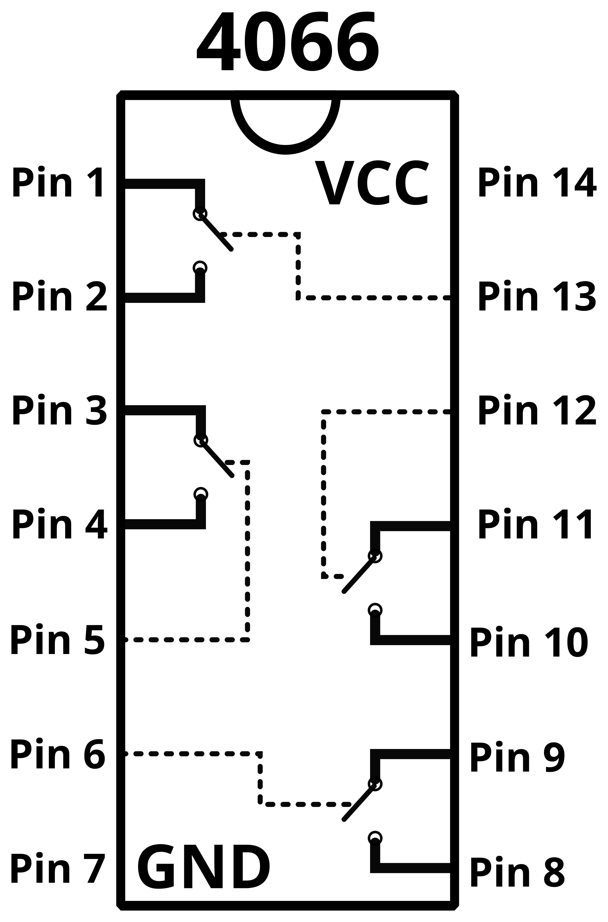 Previously we’ve looked at the 4051 8-way switch and used it to select one from eight possible inputs. The limitation with the 4051 is that it’s only possible to select one from the eight inputs at a time. The 4066, on the other hand, is just a set of four switches. This lets us build setups where more than one input channel is active at a time.
Here, we’ll be using the 4066 to route two sound inputs each into one or both of our right and left outputs. Take one voice, say a quiet one like the drum or cymbal circuit, and connect it through two 100k resistors into two switches from the 4066. The other side of each switch is connected to the left and right 4069UB amplifier circuits, respectively. When only the “left” switch is active our drum sound comes out the left side, and vice-versa. When neither is active, the drum is silenced, and when both are active the drum will be centered in the stereo field, and a bit louder because you’ve got two drum signals in place of one.
We can repeat the same hookup for a second voice. Let’s assume that the second voice is a loud one, like a VCC-to-GND square wave or similar. For comparable volume level with the quieter sound, we’ll need to run this loud input through a larger resistor, say 1 MOhm. Any of these input resistors can be substituted with a potentiometer if you’d like smooth control of the volume level. And again, if any of the input signals are not centered around VCC/2, pass them through a 1uF cap on their way into this circuit and don’t forget to de-couple the output or use a virtual ground.

Now we can turn on and off the left and right channels for inputs A and B with logic-level voltages at the four inputs.
Getting Fancy
Now don’t forget our sequencing tricks from previous sessions. For instance, adding a 4017 counter to the mix would allow us to trip the different 4066 switches in order by tapping off of the counter stages. Panning two similar sounds (triangle wave and square wave in the demo below) between the two stereo channels in sequence or in pairs can make a neat, evolving sound texture out of very simple sources.
The 4066 switch makes a great general-purpose control for turning on and off a given voice. We’re using it here for panning effects, but you could also imagine hooking up four different pitch oscillators to the four switches and playing a simple tune just by selecting which notes make it through the switches at a given time.
And as you can hear in the videos, the 4066 switch works fast enough to be fed audio signals into the switch control port. Every time a jumper wire is pulled out of the board, it couples with the 50 Hz power-line frequency and makes more overtones as the input frequency and the 50 Hz switching frequency mix with each other, for a sound that’s not unlike what you’d get by running both signals through an XOR.
An on-off switch seems like a humble device, but it’s very broadly useful. So have some fun switching elements on and off in the stereo field here, but don’t think that you’ve seen the last of the 4066.
Next Session
As promised previously, next session we’ll start getting into a little more advanced Logic Noise circuits, and in particular getting into voltage control. The 4046 phase-locked loop IC has a small voltage controlled oscillator inside it (among other parts) so it’ll be our first stop. We’ll make sweeping pitches without turning knobs. Stay tuned!
PS: Parts List
A number of folks have asked for a parts list for the Logic Noise series. Here goes.
I’ve tried to keep the variety of parts used as low as possible, for instance by using 100k resistors as a standard value whenever they’ll work. All potentiometers we’ve used so far are also 100 kOhms. Capacitors have been between 10nF and 10uF, a fairly normal range, and we’ve used 100nF caps for almost all of pitch-determining applications. The point of all this is that you can buy these parts in large enough volume to hopefully get a discount.
ICs / Actives:
All of the 4000-series ICs are available under different names from different manufacturers. Most of the chips in my drawer are from TI or Fairchild, but I’ve got a bunch from ON and NXP. Most of the time, they’re interchangeable:
CD4xxx from TI and Fairchild Semiconductor
MC14xxx from ON Semiconductor
HEF4xxx from NXP
In buying ICs, I almost never buy one, and for most of these parts the volume discounts start at 10 pieces. Take the quantites below to be rough suggestions. You can never have too many useful parts.
- 10x 40106 hex inverter (you’ll use these everywhere)
- 10x 4069UB inverter, amplifier (UB is crucial)
- 4x 4051 eight-way switch
- 4x 4066 quad single-pole switch
- 2x 4040 binary counter
- 2x 4017 decimal counter
- 2x 4015 shift register (or 4094 if you won’t use the dual-clock functionality)
- 2x 4070 XOR
- 2x 2N3904/2N2222/BC548 or similar NPN signal transistors
(and soon:)
- 2x 4046 PLL
- 2x 4007 misc gates
Passives:
- 100x signal diodes, e.g. 1N4148.
- 100x 100k Ohm resistors (our mainstay)
- 100x 10k Ohm resistors (also useful)
- A handful of odd-value resistors here and there. Get an assortment if you don’t already have one.
- 100x 0.1uF (100nF) capacitors. Ceramic/MLCC is fine.
- 100x 1uF capacitors. ditto
- 10x 10nF capacitors, ditto
- 10x 10uF capacitors, electrolytic, 16v is fine.
- 10x 100uF capacitors, electrolytic, ditto.
Potentiometers:
- 10x 100k Ohm linear potentiometers (this is where most of your budget will go, and honestly 20 wouldn’t be too many)
- 1x 100k stereo / dual potentiometer for bass drum circuit
Misc:
- Some pushbuttons, but again you’ll never have too many
- Breadboard and a lot of breadboarding wires
- 9V battery and clips to connect to breadboard, or power supply
- Powered computer speakers or amp and speaker
- 3.5mm audio jack / stereo cable for output


Ok. That is totally cool.. Equal parts nostalgia trip and solidification of understanding of concepts.
Im gonna be that guy, but if this was scaled in some octave/volt scheme, it would be much more intriguing for me!
Damnit! Next session (4046 VCO) is going to be volts/Hz rather than volts/octave. Maybe that will suffice?
Rene Schmitz has a decent, simple exponential converter (http://schmitzbits.de/vco4069.html) circuit that would fit in very well with the Logic Noise series. (And you can skip out the entire lower half of the circuit if you’re only interested in sawtooth waves.) You could probably just strap his expo part onto one of our simpler 40106 oscillators (sawtooth, w/diode) instead of using the 4069 as he does.
I think someone like Thomas Henry has a volts/octave 4046 oscillator design. (Bam! Duck-duck-go! http://www.birthofasynth.com/Thomas_Henry/Pages/X-4046.html) I’ve never built it, but it looks like a tweaked-for-high-frequencies version of the same one Rene used.
There. Spoilers for the next column that I haven’t even started writing yet. Worse than Game of Thrones.
The dragons are coming…. ;)
Looking forward to it!
I remember your initial comment about avoiding scaling because it is a much less accessible topic than Simply making noises, and I agreed with it at the time, but then I see how far you have taken this, and want it to be a ‘real music instrument’, you know?
Thanks for the leads on some scaling circuits – I cobbled together some years ago with op amps, to work with a monolithic function generator IC – which ive sadly forgotten the part number for.
Inspiring series, I would be surprised if your efforts have not sparked at least one young future synthesizer designer’s interest!
Any sort of scaling would be fine, by the way, I think.
A arduino based midi interface. Might violate the spirit of the series so far, but I think it would be another step towards truly inspiring those who want to make functional “normal” music devices, but are stymied for whatever reason.
I’m currently putting the finishing touches on a simple 40106 based FM bass pedal synth. I used the foot pedals from an old organ. It’s basically a row of switches with a common input. By connecting each switch to a trimpot voltage divider and running the resistor part of the oscillator through it I was able to tune it to a chromatic scale. It holds tune pretty well. Careful adjustment of the capacitor value to limit the tuning range is a must. Multi-turn trimmer are also very helpful.
I used a similar approach with an Arduino based granular synth. I used a keyboard from a Hammond organ and a voltage divider array to make the synth play a chromatic scale. Since the sketch was written to output a stepped chromatic scale controlled by a pot, it was really easy to tune the voltage dividers.
http://www.instructables.com/id/Adding-Keys-to-an-Arduino-Synth-The-Blacklord-The-/
Applause at trying to collect these for all… but I find a lot more for myself. And you have a HAD slant that is like HAD did something…..
I’m out.
I know, right? Putting all the info in one place with decent explanations, creating a custom PCB layout tying all the components together and making that layout available for free- what a bunch of jerks!
That’s it- I’m going back to Make. Just the other day someone in their comments told me how to make $50,000 a month working from my laptop. That’s info I can use.
How could you record on a smartphone’s 3.5mm trrs jack, from another smartphone’s 3.5mm headphone output?
That 4-connector TRRS plug is a PITA. My laptop and of course my phone use them.
First, you’ve only got one input channel, so if you want stereo you’re out of luck. I had to dig out my old USB stereo DAC to record audio for the videos this week b/c of that.
Next, depending on the phone / implementation, it may expect fairly small signals (like mic level) through the input like my phone, or it might be auto-switching between mic/line level like my laptop. If you need mic level, you’ll need to reduce the voltage output by something like a factor of 50, down to ~2 millivolts peak-to-peak from ~1 v.
Finally, I’ve seen two pinouts for the TRRS plugs, and you’ll have to figure out which pin the mic/line input is on. No biggie, just put signal on all of them until you get something.
Most headphone outputs on smartphones double as mic inputs. Shouldn’t be hard.
Interestingly enough, I can plug my headphones into the mic input jack on any of my mixers and speak into the headphone speaker/driver, and get audible voice back through my mixer. Works great when having mic problems in a pinch…
You know what I’d like? A chronological list of links to each episode. Ideally this list would be at the end of every episode, or else, below each episode a link to the next episode. Putting an episode number in the title would help as well.
The way it is now it’s just not easy to follow the series from the start. Which is a shame for such an excellent series. Perhaps one of the editors can fix this?
What are the drum sounds made from? What is the IC that is used?
Hi, great series!
I need to output some square waves to both speaker and headphones.
I tried the virtual ground idea, it works’ but it seems the output from the speaker is too low, while on the headphones it’s too high. Any help? Thanks