Welcome back to the final chapter in our journey exploring two-stage tentacle mechanisms. This is where we arm you with the tools and techniques to get one of these cretins alive-and-kicking in your livingroom. In this last installment, I’ll guide us through the steps of building our very own tentacle and controller identical to one we’ve been discussing in the last few weeks. As promised, this post comes with a few bonuses:
Design Files
- The Almighty Bill-o’-Materials
- Vector Drawings for laser cutting
- DXF files pre-offset (0.003″)
- DXF files original
- STL Models for 3D Printing
- Original Tentacle CAD Model Files
- Original Controller CAD Model Files
Depending on your situation, some design files may be more important than others. If you just want to get parts made, odds are good that you can simply cut the pre-offset DXFs from the right plate thicknesses and get rolling. Of course, if you need to tune the files for a laser with a slightly different beam diameter, I’ve included the original DXFs for good measure. For the heavy-hitters, I’ve also included the original files if there’s something about this design that just deserves a tweak or two. Have at it! (And, of course, let us know how you improve it!)
Ok, now that we’ve got the parts on-hand in a pile of pieces,let’s walk through the last-mile tweaks to making this puppet work: assembly and tuning. At this point, we’ve got a collection of parts, some laser-cut, some off the shelf. Now it’s time to string them together.
Tipping our Hats to the Hallmark of How-Tos
In the last year, both the Crazyflie assembly instructions and the Formlabs printer maintenance docs have done something novel with their step-by-step instructions. They’ve mixed video clips into their instructions to better showcase a process. Whether that’s sliding a motor onto a quadcopter frame or sliding the build platform out of the printer for cleaning, these clips nail exactly one thing: the specific steps of a short process. In writing these docs, I’m tipping my hat to these folks who showed me just how informative a well-timed video clip can be.
All right–let’s get started!
Controller Assembly
Each Controller is basically two pulleys rotated and stacked on top of each other. We’re assembling everything ourselves here, but don’t fret–I’ll highlight the details to get you feeling comfortable enough to build one at home. (Curious to know why I opted for a mechanical solution? Check out Part II in this series.)
1. Assemble 4x Pulleys
To get the order-of-operations right, have a look at the quick clip on the right. Unfortunately, those parts won’t just install themselves! Getting those parts installed is a matter of using the right tool.
Components:
- qty 2: 4-40 threaded heat-set inserts
- qty 16: M2 threaded heat-set inserts
- qty 44: 9/16-in long 0.125-in diameter semitubular rivets
- qty 8: outer_pulley_plate
- qty 8: inner_pulley_plate
- qty 16: 612K-ND angle brackets
- qty 16: 3/16-in 4-40 buttonhead socket cap screw
- qty 16: small washers
Tools:
- rivet press (or handheld riveting tool) for semitubular rivets
- soldering iron
Detail: Rivets
I’m using a miniature rivet press in my home shop, but you may be able to score some time on one at your local hackerspace.
Detail: Heat-Set Inserts
Getting the heat-set inserts into your part may seem a bit daunting, but it’s actually fairly straightforward. With the soldering iron set to 250 C, gently work the inserts into the part. Don’t press down on the iron! Instead, gently wiggle the tip, and let the weight of the iron work the insert into the part. Each insert takes about 15-20 seconds to set, so don’t feel too hasty!
Detail: Wire Clamps
To get the order of operations right on this feature, have a quick look at the assembly video. Keep in mind that the wire rope will slide between the washers and the upper angle bracket in a later step.
2. Install Inserts in 3x Pulley Plates
Heads-up! Three of our plates have several insert features. Warm up that soldering iron again; it’s time to get a few more satisfying thrills whilst melting brass into plastic. I’ve called out each “screw-thread-insert” (STI) location in the diagram below. These holes have been sized to specifically accommodate the heat-set inserts.
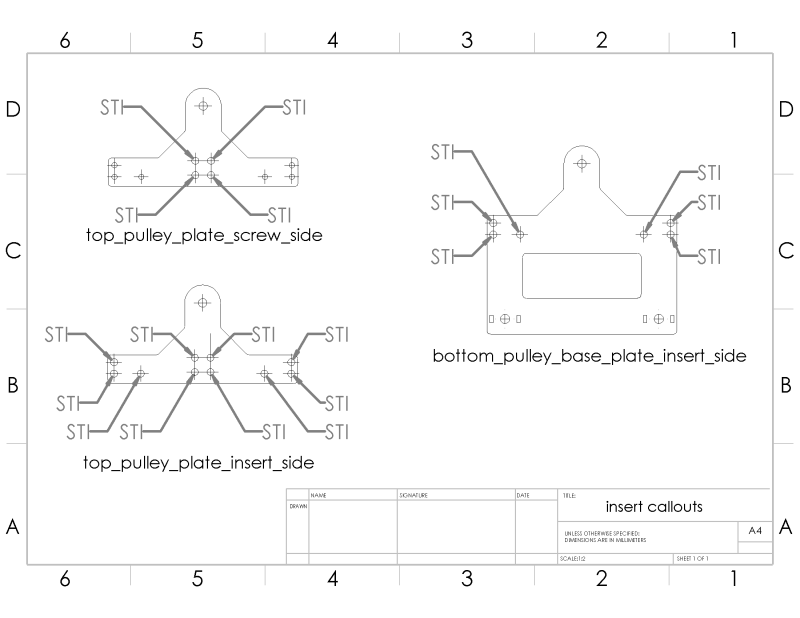
Components:
- qty 40: 4-40 Heat-Set Inserts
- qty 2: top_pulley_plate_insert_side
- qty 2: top_pulley_plate_screw_side
- qty 2: bottom_pulley_base_plate_insert_side
Installing these inserts is just like we did previously for the pulleys. Give yourself a few minutes to complete these, but be gentle as before.
3. Countersink Bracket Plates
These plates will be the main junction between a controller’s upper and lower pulley. Create countersinks in the following locations.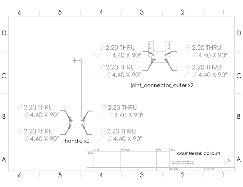
Components:
- qty 4: handle plates
- qty 4: joint_connector_outer plates
Tools:
- Countersink + Countersink Cage and hand drill (or drill press) OR
- Countersink with drill press that has a hard-stop feature
 Detail: Countersink Depth Tolerances
The screws that slide through the holes in these plates need to engage a threaded insert that’s either one or two plates deep. Countersink these plates such that the screws are, at minimum, flush with the plate. Too deep is OK, as long as the screws don’t bottom-out past the threaded insert.
In more detail, there’s quite a bit of wiggle room on the depth of the countersink, and here’s why. Our plates come in increments of 3.175 mm. Our 6mm screw will engage the threads after passing through 1 plate. Our 8mm screw will need to pass through two plates before it engages the insert in the third plate. What this means is that the total distance of travel for the 6mm screw is two plates’ worth of thickness, or 6.35mm, and three-plates-worth of thickness, or 9.525mm for the 8mm screw. Hence, while the 6mm screw has about 0.35mm of wiggle room, and the 8mm screw has a whopping 1.5mm worth of wiggle room before either screw bottoms out.
4. Join Pulley Sections
Components:
- qty 4: assembled pulleys
- qty 2: top_pulley_plate_insert_side
- qty 2: top_pulley_plate_screw_side
- qty 2: bottom_pulley_base_plate_insert_side
- qty 2: bottom_pulley_base_plate_screw_side
- qty 4: pulley spacer
- qty 4: joint_spacer
- qty 4: joint_connector_outer
- qty 16: 6mm M2 socket cap flathead screws
- qty 16: 8mm M2 socket cap flathead screws
- qty 4: shoulder screw
- qty 2: 8-32 nut
- qty 4: 3D-printed cable_insert_bracket with inserted ferrules
- qty 4: .5-in 4-40 female threaded standoffs
- qty 12: .25-in 4-40 socket cap screws
- qty 32: 3/16 4-40 button-head socket cap screws
- qty 16: 612K-ND angle brackets
Tools:
- metric allen keys
- imperial allen keys (I tried not to mix-and-match Jurassic and Metric…. but off-the-shelf components don’t come in every flavor, yo.)
Detail: Order of Operations
For each controller, I’d recommend building up the upper and lower halves separately and then joining them together afterwards. To secure both halves, we’ll be using those classy 612K-ND corner brackets that I mentioned in the previous installment.
Detail: Pulley Bore Diameter Tolerances
The shoulder screws should slide easily through the pulleys. If that’s not the case, feel free to drill them out with a 0.1875″ drill bit.
Detail: VSlot Extrusion Mating Points
Once assembled, these cable controllers can very easily be connected to two rails of Open Builds VSlot 20×20 extrusions. This features lets the user find a controller spacing that’s comfortable for their shoulders.
All right–we’re good to go for the controllers! Let’s move to the tentacle.
Tentacle Assembly
In this next section, we’ll walk through assembling the tentacle and hooking it up to a manual controller.
1. Prep Wheel Hubs
Components:
- qty 18: wheel hubs + set screws
- qty 18: Delrin vertebrae segments
- qty 2 x 18: 4-40 x 3-16 in. button head screws
Tools:
- Drill press
- 0.125″ or 4mm drill bit, depending on tentacle core diameter
- vise
Each vertebrae segment consists of a wheel hub, a delrin plate, and two screws. (Yes, you can put in all four screws if you like, but the last two are unnecessary and just add extra weight.) Fashion yourself 18 of these nuggets.
Detail: Hub Diameter
Depending on what size core you’re using (4mm flexible shaft vs 3.175mm speedometer cable), you may need to widen the hub axle diameter to accommodate the core. By clamping these hubs in a vise, you can drill them out to the larger diameter of choice.
2. Cut Wire Rope to Lengths
Components:
- qty ~25 feet (7.62 m): 1/32″ diameter wire rope
- qty 4: Wire “Termination-Style” Crimp Ferrules
Tools:
- Wire Rope cutters These must be wire rope cutters. Don’t destroy your electronics snippers only to discover that they don’t work :(
- Hefty Wire Cutters for spring guide only
- Wire rope crimpers for small ferrules
- Optional: mini blowtorch
- Cut down eight lengths of wire rope each at 3-ft (914 mm) lengths.
- Optional: On one end of each wire rope, blowtorch the tip until it becomes white-hot for about 8 seconds; then let it cool. This quick “heat treatment” will prevent that tip from fraying as easily.
- Gather up 4 of your 8 cables. On the un-torched ends (or either end if you didn’t blowtorch them), crimp on a “termination-style” ferrule.
3. Assemble Inflection Point Vertebrae
Components: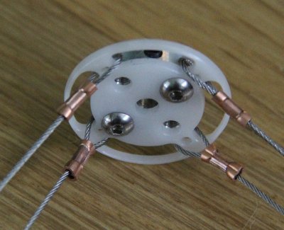
- qty 4: Wire Loop Ferrules
- qty 4: uncrimped remaining wire rope lengths
Tools:
- Wire crimpers
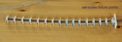
- Gather up the 4 remaining uncrimped wire rope lengths.
- On each end, loop the wire through the vertebrae at one four horizontal segments (See image above) and then back on itself.
- Slide the loop ferrule onto the rope and loop the short end of the rope back into the ferrule and crimp
4. Prep Upper Stage Cables
Components:
- 8 vertebrae (plus-or-minus a few)
- qty 4: wire ropes with end-stop style crimp
- qty 1: speedometer cable or (better) flexible shaft cut to 24 inches (610 mm)
- qty 4: continuous-length extension spring (aka: spring guide) at 24-inch (610) lengths
Tools:
- 1.5mm allen key
Ok, two TODOs in this department: wire and sleeve.
- Slide one vertebrae to the tip of your flexible core material.
With the allen key, secure it firmly to the tip. - Slide the remaining (7) vertebrae into the core
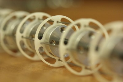 material and space them evenly about an inch apart. With
the allen key, secure then gently. (We’ll secure them down more permanently later.) The core material should fill up with vertebrae for about 1/3 of its total length at this point. - For each of the four wire ropes, slide the uncrimped end from the holes in the top vertebrae down through the corresponding holes of each sequential vertebrae. Remove all the slack such that the ferrule connects with the top vertebrae.
5. Prep Lower Stage Cables with Inflection Point
Components:
- 7 vertebrae (plus-or-minus a few)
- Inflection point vertebrae with attached wire ropes
- Slide the inflection point vertebrae into the core material and secure it gently, evenly spaced just like the other vertebrae.
- Slide in 7 additional vertebrae and secure them gently like before. Slide the 4 wire ropes that start at the vertebrae through the corresponding holes in each of the lower vertebrae segments. The total vertebrae count at this point should span about 2/3 of the total flexible core material length.
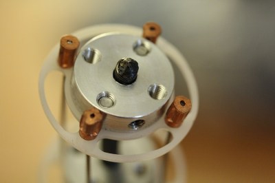
6. Attach the Base Clamp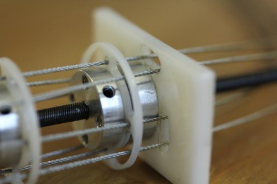
The key to a good puppeteering act is to have the tentacle base rooted down firmly. Right now, I’ve got a temporary solution, an extra square clamp that’s rooted to the base. There’s no magic here, just an extra wheel hub and plate that are both closely butted up against the bottom segment.
7. Adjust vertebrae Spacing/Alignment
Ok, now’s the time to tighten down those vertebrae, but, first, we’ll give ourselves a chance to better align them. For each half of the tentacle, ensure that each segment is well-aligned with its fellow segments in that stage. Loosen and adjust as necessary. Then, tighten down each segment.
8. Sleeve Wire Ropes
Components:
- qty 4: continuous-length extension spring (aka: spring guide) at 24-inch (610) lengths
- qty 4: continuous-length extension spring at 18-inch (457 mm) lengths (You can cut these with a hefty wire cutter)
Tools:
- a hefty wire cutter
Almost there! Our extension spring selection above will become the cable conduit housing in this design. Four cable conduit housings will terminate at the bottom of the tentacle. The other four will terminate halfway up the tentacle at the inflection point, traveling through the lower section along the way.
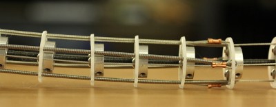
- Slide the four longer cable conduit housings into each of the four longer wire lengths. Each of these housings will slide through the body of the lower tentacle through each of its four large gaps. Slide these cable conduit housings up to the inflection point where they can extend no farther.
- Slide the four shorter cable conduit housings into the four shorter wire lengths until they terminate at the base of the wires.
Nice–time to wire it into the controller!
9. Attach to the Controllers
On our tentacle, each degree of freedom gets two complementary cables and each stage gets two degrees of freedom. On the controller-side, each pulley will join a pair of complementary cables to give that degree of freedom its full range of motion. (Confused? No worries! Check out Part I.)
Now that we have a mess of cables and housings on our hands, go through this mess and pick out each degree-of-freedom’s cable pairs. (Zippy tie them or tape them together temporarily to keep the mess in check.)
For each of these pairs, slide the cable and its complement into opposite 3D-printed conduit holders and string them under the first angle bracket in the pulley’s wire crimp. Take out all the slack on these cables. These need to be tight! That is, keep feeding the wire rope through the wire crimp until the cable conduit bumps into the 3D-printed conduit holder. Screw down the wire clamp for now without worrying too much about tension. Repeat this procedure for each cable pair.


10. Tension Cables
At this point, it might actually help to have the controller dissassembled into the two main components.
From here, with your two hands, apply some tension to the counteracting wire ropes and use one of your partner-in-crime’s two hands to screw down the wire clamp with an Allen key. Alas, this is the second time whilst hacking that I find myself pondering over when they’re finally going to release “third-hand” surgery. (The first case, of course, being soldering… Hand 1 holds the solder. Hand 2 holds the iron. Hand 3 holds the tweezers with the component. Truly, it’s a no-brainer for another arm here.)
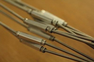 This method of tensioning works well enough, but there’s a far better method if you’re willing to shell out a bit more cash for components. Instead, I propose constructing internal extension-spring tensioners from two vented screws and a standoff. Simply by unscrewing the vented screw, one can increase the tension along the cable. No third hand required!
For the vented screw jig pictured, I’m using McMaster-Carr’s 4-40 vented screw section, which has a vent diameter that’s just larger than 1/32″ diameter wire rope. This use case finally merits a legit reason to pick up a few of those “vented screws” on McMaster-Carr that I’ve been eyeballing for years every time I land on their catalog’s screw page.
11. Clamp down the Base
Don’t forget: getting that convincing, fluid tentacle movment comes from having the base rooted down firmly such that the entire spine resists twisting at the base. I’m using a small vise that clamps onto the remaining tentacle length to do the trick for now, but this section deserves a bit more design effort. While a vise will totally work, feel free to keep us all in the loop on more clever fixturing methods!
Outro
If you’ve made it this far with a sparkling new tentacle to boot–congrats! Now go make an army of 20, rig them up to a few dozen servos, and set them to the beat of some hip 70s disco. For the folks that have read this far, I hope you can take away a few new techniques-of-the-trade that you can bring to your next after-hours, robot design-a-thon. Finally, thanks for joining me in the last few weeks as we tour these strange beasts. Writing these last few posts has been a blast.


In b4 the tentacle pr0n comments. :-D
You have to admit that joining the logical custom 3d printed silicone toy approach to these would actually be pretty neat to explore. Could, in theory, even have medical uses.
https://hectocotyli.files.wordpress.com/2010/05/tentacletools.png
Comment reported; gross.
Please delete.
It’s just a tentacle made from silicone. Nobody said you had to think, do or explore doing anything you don’t want to with it. There are not much better form factors to go on the end of this device if you want it to be usable. It’s literally a mechanical tentacle arm.
@ RW
Beat me to the comment :’)
Can I get this done before Halloween… It would be glorious to use this to drop goodies into TorTer’s bags (even without a fancy gripper—next topic)?
Maybe! Biggest lead time is those flexible shafts from AliExpress, which takes just under two weeks. Everything else ships pretty quickly. :)
Mold some rubber octopus suckers onto them and use a vacuum pump. :D
Excellent!
Horrible terrifying Jack-O-Octopus to chase them away.
Ah, that’s the answer!! Stick one piece of candy to the end of the tentacle, and since the kids will run away before you need to release it into their bags, no fancy mechanism is needed. Just in case there’s a brave(r) one among them, attach a “bloody” piece of cloth near the end of the tentacle.
Imaging if you attached a camera at the end of it.
There is one with a camera and a laser cutter on it.
Kick ass! great job. I would recommend it to a friend.
Amazon review: Went haywire and throttled mother in law 10/10 would buy again.
Where’s the small pocket knife taped on the end?
LOL :P
I haven’t tried making one yet; going to try a simple one stage using poker chips.
Shouldn’t it be: 1 Tentacle Base Plate (Delrin 0.125″) and 16 Tentacle segment (Delrin 0.0625″) in the BOM?
Whoop–fixed! Thanks for the heads-up!
I’m gonna four of these attached to a harness, with a neural interface. It’s, uh, engineering class… by the way, anyone know a way to deal with BIG spiders? Asking for a friend.
Sneak up behind it, get it in a head lock, then stab at the neural clusters behind it’s eyes… … but the real big ones, can’t get your arm around, so try and do a surprise double handed plunge with something long enough, like a claymore.
Hmm, claymore, I think I can work with that.
Depends on the colour? If it’s a black one with white marking try making loud noises. If it’s a red and blue one you might be out of luck :-( Good luck, Mr Oc.
Thank you.
Yeah, the red and blue ones are the worst…
Here’s a papercraft tendon driven arm to whip up while you’re waiting for parts to arrive: https://www.robives.com/blog/tendon_driven_arms
I built one of those out of aluminum and penumadic also cable worm drives as well years a go.
i don’t want to know what he do with it xD
How many oz-in of torque would a servo need to drive this?
What are the chances of purchasing a tentacle cable mechanism controller assembled and boxed?
If so can you give me a price ?
Regards,
Roby
Hi Joshua,
I’m really fascinated by your work and wish to build one. Can you please help me with some governing rules for deciding the diameter of controlling pulley with respect to the diameter of the vertebrae (if it exists at all)?