We’ve talked about Ethernet basics, and we’ve talked about equipment you will find with Ethernet. However, that’s obviously not all – you also need to know how to add Ethernet to your board and to your microcontroller. Such low-level details are harder to learn casually than the things we talked about previously, but today, we’re going to pick up the slack.
You might also have some very fair questions. What are the black blocks near Ethernet sockets that you generally will see on boards, and why do they look like nothing else you see on circuit boards ever? Why do some boards, like the Raspberry Pi, lack them altogether? What kind of chip do you need if you want to add Ethernet support to a microcontroller, and what might you need if your microcontroller claims to support Ethernet? Let’s talk.
Transformers Make The Data World Turn
One of the Ethernet’s many features is that it’s resilient, and easy to throw around. It’s also galvanically isolated, which means you don’t need a ground connection for a link either – not until you want a shield due to imposed interference, at which point, it might be that you’re pulling cable inside industrial machinery. There are a few tricks to Ethernet, and one such fundamental Ethernet trick is transformers, known as “magnetics” in Ethernet context.
Each pair has to be put through a transformer for the Ethernet port to work properly, as a rule. That’s the black epoxy-covered block you will inevitably see near an Ethernet port in your device. There are two places on the board as far as Ethernet goes – before the transformer, and after the transformer, and they’re treated differently. After the transformer, Ethernet is significantly more resilient to things like ground potential differences, which is how you can wire up two random computers with Ethernet and not even think about things like common mode bias or ground loops, things we must account for in audio, or digital interfaces that haven’t yet gone optical somehow.
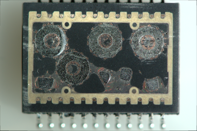 If you don’t see the transformer blob next to the Ethernet socket on your board, you might be thinking that your device has skimped on this part somehow, but that’s not the case. If you’re running Ethernet outside of your device, a transformer has to be present, which means that the RJ45 (8P8C) connector is hiding the transformer instead.
A RJ45 jack with integrated magnetics is colloquially referred to as “magjack”, and you’ll have seen one if you’ve ever seen a Raspberry Pi. They might not always be as cheap as individual Ethernet transformers combined with magnetics-less 8P8C sockets, which is why routers, switches and laptop/desktop motherboards rarely ever use them. However, they’re simple to add, and they’re great at saving board space, which is why you will see them on single-board computers and microcontroller boards.
If you need some Ethernet transformers, you can buy them, but on a short notice, harvesting them is more than acceptable. Now, you have to be mindful, of course. One of the parameters of Ethernet transformers is a turns ratio, which can be different depending on the Ethernet chip in use. If you’re using magnetics with a different turns ratio, it might not work, or it might make the chip in question very unhappy; consult the datasheets!
There’s a lot to Ethernet magnetics, including tricks like capacitive coupling, where you can situationally avoid them altogether in very specific situations. We will go through the magnetic intricacies next time, but for now, they bring us to an interesting question. When a microcontroller says that it has an Ethernet port, what does it even imply? Is it enough to add a transformer, or would it need something else? It depends – let’s learn about it!
Two Different Meanings
There are two parts to Ethernet support in terms of hardware. First, there’s the MAC – that’s a block of hardware taking care of the Ethernet protocol logic. You can’t connect it directly to a transformer, but you can connect it to a PHY. The PHY works on the physical layer of Ethernet, it’s the piece of hardware that takes prepared Ethernet packets and translates them onto the wire. Often, MAC and PHY are just two different areas on a single chip, let’s say, in desktop and laptop Ethernet chips, but just as often they’re separate.
 If the MAC and PHY are ever separate in your device – say, the MAC is inside your ESP32 chip and the PHY is external, – the MAC will be will be using an interface called MII or GMII or RGMII or something along these lines. It’s a parallel interface, of the kind you want to layout carefully, because it runs fast.
If your chip says that it supports Ethernet, that can mean two things – either it has a MAC and a PHY inside, or it only has a MAC. If the device is you’re playing with is a more networking-oriented chip, say, something like a Carambola or Onion Omega board, you will have the MAC+PHY combo – just wire up a transformer of some kind, even a magjack, and you are ready to go. If you’re looking at a microcontroller with Ethernet support though, say, an ESP32 or some STM, or the Pine64’s Ox64, it’s way more likely to just have a MAC, so you will have to add a compatible PHY to your circuit before you can start wiring up the transformer.
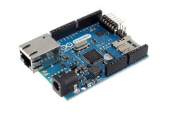
So, Ethernet support for your favorite piece of silicon might mean straightforward wireup, or it might require an extra chip. Thankfully, there’s no shortage of Ethernet-equipped designs to borrow things from – here’s the Olimex ESP32 design for instance, open-source and giving you a circuit known to work in production. Just be careful taking PoE information from Olimex ESP32 boards – their PoE implementation, is, let’s say, situationally useful. Which is why there’s warnings on the page about USB programming, but it’s a great start still!
A Sprinkle Of Resistors
Of course, there are plenty of schematics and reference designs to copy from, and if you do, you might wonder – what are the passives shown inside a magjack schematic, or visible on a board right next to the magnetics? Chances are, you are looking at the Bob Smith termination.
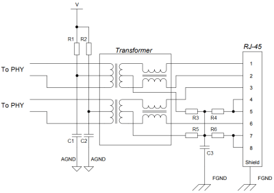
Bob Smith termination is something you do for unterminated Ethernet pairs at 10/100Mbps, which you will likely have to work with. It shunts the unused two pairs, both connecting the two wires of each pair together so that the entire pair is treated as a single wire, but also brings the pair to a certain voltage so that any noise induced onto it over the length don’t overlay onto signals on the actually used pairs.
Also, this is one of the things you might burn out if you plug a passive PoE-enabled cable – the resistors will shunt the DC path; which is why PoE-compatible magnetics add extra capacitors in series with each resistor.
On the other side, you will see pullup resistors on the center taps of the active pairs, and capacitors to ground. Omitting either of these will cause your devices to get unhappy, so if your PHY releases magic smoke, or if your Ethernet link glitches out every now and then, you will look back and wish you added them – and it costs nothing to add footprints for them that you can populate later.
Next time, I’d like to show you open-source designs and walk you through a few of them, pointing out things that are there for a reason that you might not be aware of. There are things like isolation perimeters, shield connection, Bob Smith termination values, polarity swaps and PoE tap ways, that you likely want to talk about, and I will highlight appnotes that you’d benefit from reading through, too!
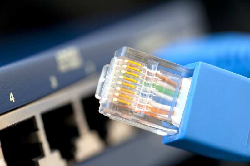
Featured image: “10base-T” by [gratuit]


The single pull-up resistor is not universal. More typically, I’ve seen individual 49.9 ohm resistors pulling up to the supply on each leg of the differential pair, with the center tap of the transformer connected to the supply. And pretty much, EVERY time, the cap on the center tap needs to be very close to the transformer itself.
Yup. But as always, one should follow both the MAC’s, PHY’s and MagJack’s datasheets.
The MAC has nothing to do with the physical connection, other than relaying configuration information (via MDIO). IIRC, some PHYs will make a connection with no MAC present.
The choice of the magnetics is driven by the PHY (and regulatory/conformance items). The use of a pair of resistors is most common because it better terminates common and differential modes, and also supports auto-MDIX (where a 10/100 connection will swap TX and RX). I’ve also seen PHYs that require a series resistor pair, with the center point connected to GND via a capacitor.
I’d say not just some, but most PHYs. That’s how a basic media converter works – two of thdm back to back
Where and how you do those pull ups / termination resistors depends on how the output of the PHY is built. Current-mode and voltage-mode outputs need different termination.
I would have mentioned SFPs, a good example of why you would split the MAC and PHY into separate devices.
I know it is mostly dead but I would love a article series on ARCNET. You can even use RS485 as the physical layer officially.
Nice article. Very informative.
Can you please elaborate on a follow up article about the myriad of MagJack configurations and magnetics in general?
It has always puzzled me which one to choose and if other types not mentioned in the PHY’s datasheet could be compatible or not. Sometimes one has a MagJack laying around but unsure if that will work on any PHY. Thank you!
take a look at the PHY datasheet. It usually explains the connections. TI ones often show multiple magnetics configurations – just match the right one with your MagJack.
Can you include some designs in your next article for doing Ethernet between two chips on a single PCB (MAC to MAC and/or PHY to PHY)? I’m thinking about doing this between a Pi CM4 and an ESP32 to control ESP32 firmware (from the Pi) that has a REST API over Ethernet. Thanks!
This is possible, though has a bunch of limitations. for PHY-PHY, (look for transformerless/magneticless) You must capacitively couple, use the terminations at each end, and turn off autonegotiation. My experience has shown range is not particularly great- a few feet of FR4. Transformers actually do quite a bit of filtering that the PHY expects.
MAC-MAC is also possible, but more picky, as you need to have a MAC that would accept a clock- only one side of the link can provide the clock signal. Range will not be great- you will have a bunch of signal integrity issues to work out. I would not really want to try it for more than a few inches. I worked with a design that was a maybe 10 inches of MII between the MAC and PHY in a traditional setup- I think that was pushing the signal integrity limits (at Gigabit speeds).
For MAC/MAC it just depends on what the bus is. If you want to push gigabit over a PCB, doing it with SGMII rather than GMII/RGMII is a *lot* easier because gigabit transceivers on devices pretty much are PHYs already.
Although I’m amused by “a few feet of FR4” – at that point just set it up as a flyover with connectors on both sides and run with a high-quality cable (2 sata cables, for instance).
The few feet of FR4 was (20 years ago) a blade server. Came from a switch, over a midplane, to a pluggable 100mbit management module (1 per chassis). The management SoC had an integrated MAC/PHY (the same SoC across the much broader product line, so could not change it). Cost optimized (to a point), so had to ditch transformers. An extra cable as you suggest was out of the question- everything had to go through the same high speed blind mating connectors- one action to plug/unplug the card.
I remember this distinctly as I had to verify the operation of the concept (confirm the signal, verify an acceptable BER). We had to stay with FR4, as other dielectrics were too expensive for the size of the midplane.
Yeah, a lot of that would just be the product of the times: nowadays even if you were stuck with GMII/RGMII you just get a RGMII/SGMII bridge (which a *ton* of PHYs can do internally) and you can basically go arbitrary distances even on FR4 with SGMII.
It’s the same reason PCs migrated from PCI to PCI Express. PCI ends up being a Hard Problem to maintain a many-pin parallel bus at high speeds even ignoring the multidrop. Convert it to serdes and it’s just not difficult at all until you get well into the multiple gigabits range.
The RP2040 can do everything on its own (no need for external chips, just a transformer, a few resistors and capacitors, it even works on breadboard if well made).
https://github.com/holysnippet/pico_eth_doc
In the old days you could buy an MII transceiver, which you could plug into an MII port on your board. This would be useful for high-speed logging, debuggers etc., but in final product the MII doesn’t do anything (so you don’t have any spurious emissions to worry about).
Some form of MII is still used in every MAC/PHY setup- it is the standard interface between MAC and PHY, though there are modifications to it- RMII, GMII, SGMII… it is there, but not always exposed.
The standard interface is really the MDIO bus. The “MII” portion is just an acronym – there’s zero similarity between SMII/SGMII and any of the MII/RMII-type busses.
This is a good installment on understanding PHY Ethernet realities. What needs mentioning is the galvanic isolation voltage achieved the the XFRM and PCB, often being 2 to 4kV, and how to mitigate induced voltage disturbances. A nearby lightning strike (not direct, just induced) can take out the Ethernet interface, while leaving the device fully functional (minus Ethernet connectivity). Then there is standards based PoE, and proprietary (24V, 12.5 vs 25 Ohm sense resistors, etc). Definitely need for another chapter. Found this previous article gets a bit into it, but more details required: https://hackaday.com/2022/12/08/power-over-ethernet-explained/
In 10obase-T , is it possible to not connect the 4-5 and 7-8 pairs and still have a functional connection?
This series is timely for me. I have been looking at 8P8C (RJ45) mag jacks a lot in the past week to try to find one for an industrial sensor. There are endless varieties so knowing the requirements is critical. One thing that puzzles me is for PoE I can find magjacks with either internal BS termination OR with internal PoE diode bridges but almost none with both. Where they have Bob Smith “BS” termination they output the four wires (2 pairs) for power from cable side center taps and so you can use an external diode bridge to the PoE controller. For magjacks with integrated diode bridges they almost never have the BS termination (exception is one from Halo that does) and don’t allow access to add external BS termination since output is two wires from the diode bridge.
This leads me to wonder if this is due to space constraints in the jack or if there is a reason like BS termination is not useful once a diode bridge is used? Perhaps, surge protection is handled after the diode bridge so BS terms not useful and with common mode chokes in magjacks nowadays BS terms not so useful anymore for EMC?
I found so far no good explanation on manufacturer’s websites about this.
Anyone have thoughts on this?