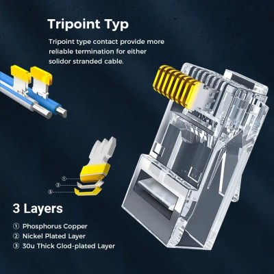
Ethernet is ubiquitous, fast, and simple. You only need two diffpairs (four wires) to establish a 100Mbit link, the hardware is everywhere, you can do Ethernet over long distances easily, and tons of the microcontrollers and SoCs support it, too. Overall, it’s a technology you will be glad to know about, and there’s hundreds of scenarios where you could use it.
If you need to establish a high-bandwidth connection between two Linux boards in your project, or maybe a Linux board and a powerful MCU, maybe make a network between microcontrollers, Ethernet’s your friend. It also scales wonderfully – there’s so much tech around Ethernet, that finding cables, connectors or ICs tends to be dead easy. Plus, the world of Ethernet is huge beyond belief. Ethernet as most of us know it is actually just the consumer-facing versions of Ethernet, and there’s a quite a few fascinating industrial and automotive Ethernet standards that flip many of our Ethernet assumptions upside down.
Now, you might be missing out on some benefits of Ethernet, or perhaps misunderstanding how Ethernet works at all. What does it mean when a microcontroller datasheet says “has Ethernet interface”? If you see five pins on an SBC and the manufacturer refers to them as “Ethernet”, what do you even do with them? Why does the Raspberry Pi 4 SoC support Ethernet but still requires an extra chip, and what even is GMII?
Transmit The Basics
Ethernet is fundamentally about point to point connections – a single cable connecting two devices. If you have multiple devices you want to tie together into a network and Ethernet is what you’ve got available, you’ll want to use a switch, or a router with a builtin switch, or something else that has multiple Ethernet ports, then do individual point-to-point links between the switch and your devices, forming a star topology network. It used to be that you could use a coaxial cables for Ethernet and wire a single cable between computers, but those days are long gone, and the speeds were low enough that the major reason to miss those times is nostalgia.
There’s two versions of Ethernet you will encounter nowadays when it comes to speed – 100 Mbps (Mbit/s), often known as 10/100 because it usually also supports the old 10 Mbps mode, and 1 Gbps, known as Gigabit Ethernet. There’s also 2.5 Gbps, slowly becoming more commonplace in higher-end consumer tech like laptops, PCs and routers, but it’s yet to grace microcontrollers and SBCs, and I wouldn’t hold my breath – 100 Mbit/s is still enough for a ton of things. 5 Gbps and 10 Gbps are apparently on the horizon, but don’t expect to link up at that speed yet, unless you reuse some server card , invest some good money into it, or take time figuring out a cheap way. Of course, that’s bits per second, not bytes – if you want to calculate maximum file transmission speed where bytes/second is commonly used, you want to divide by 8, and subtract about 5% for packet overhead.
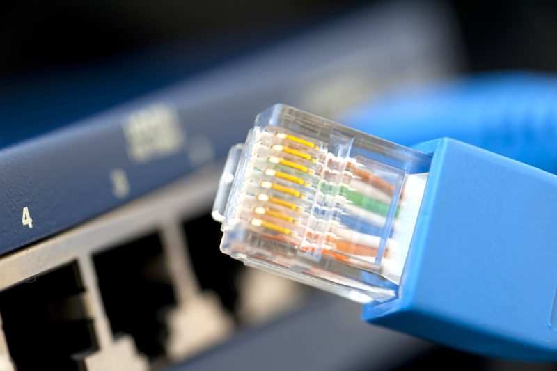
Physically, Ethernet tends to use cabling known as CAT5e, and connectors known as RJ45, with the proper name technically being 8P8C. Both the cables and the connectors are super commonly available, no end of life in sight. So, if you want to connect two boards together in a project of yours, maybe even with a shielded cable, using Ethernet cabling is a good bet – even if your project has no trace of Ethernet to be seen.
Speaking of cabling, Ethernet cables most certainly deserve their own part of the article. Let’s talk about cabling in as much detail as could be useful for an average hacker.
All The Wires
An Ethernet CAT5 cable has four twisted pairs inside of it, each one used for a separate differential pair – so, eight wires on total. Higher-speed versions of Ethernet like 2.5 Gbps will often wants higher-grade cabling than CAT5 – CAT6 or even CAT7, manufactured to a higher standard, but CAT5 (or CAT5E specifically) is what you’ll see the most of. Internally, some cables use multi-strand wires and some use solid core wires, and they work best in different scenarios. Short patch cables (known as “patchcords”) are better with stranded wiring, because it’s more flexible and easier to handle. However, stranded cables are less durable, and don’t work as well at longer distances. For more permanent and longer cabling, people tend to use solid core wiring, as it’s generally higher-quality, which helps on longer cable runs. Also, there’s different types of outer insulation – some are more fireproof, some are less toxic, and some are more resistant to environmental influence like UV light.
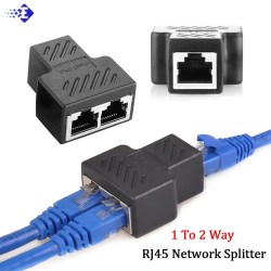
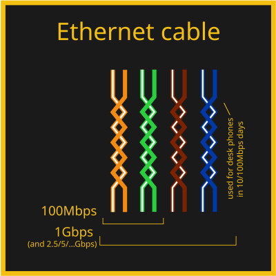 Out of the four pairs, 100 Mbps Ethernet only actually uses two of them, but 1 Gbps Ethernet uses all four. That’s why, on cheap old Ethernet hardware like low-end home routers with 100 Mbps ports, it’s not uncommon to see Ethernet sockets with only four pins out of eight – saving money by all means possible, after all, the two pairs in the cable would not be used anyway. There’s also hack potential in this, for instance, you can pull two 100 Mbps Ethernet links through a single CAT5 cable – that’s how my own Internet uplink used to work for a while about a decade ago, and that’s what the adapter pictured above does. And you can pull power through those pins in parallel with the Ethernet uplink, we’ll talk about that later, too!
Some Ethernet cables have internal shielding, but hardly anyone requires it – it’s used more in industrial or sensitive environments, and it might be required for higher-speed Ethernet standards too, but it’s rarely ever seen at home. So, most cables are not shielded, and they’re referred to as UTP (Unshielded Twisted Pair). There’s quite a few types of shielded Ethernet, which you might see referred to as FTP, SFTP, S/UTP or such – S- types (Shielded) wrap individual pairs or the cable in copper braid, FTP (Foiled) wraps them with foil, SFTP does both, there’s three-four different acronyms for each type of shielding combination, but don’t worry, you are not expected to remember this, just refer here or here if you ever need to know more. Also, don’t confuse it with SFP, that’s different! The type of shielding is typically written on the outer insulation along the length of the cable, too. If you are looking at a bundle of Ethernet cables of all kinds and you just want to find a shielded Ethernet cable for whatever reason, say, your robot’s internals, good shorthand is looking at the connector – it’s going to be metal-plated. Oh, and if you want the shield to be effective, at least one end has to actually be connecting that shield to something – many cheap devices don’t bother and use connectors fully made of plastic, with no plug shield connections in sight.
There’s only one standardized Ethernet connector, but there are a few different ways to cook it! In particular, you should know a few things about the standard pair-to-pin mappings, and how to actually terminate the cable in an Ethernet plug.
Plugs, Crimps And Mappings
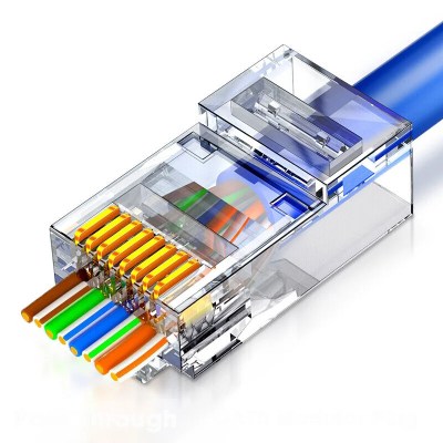
The usual Ethernet connectors are RJ45, technically correctly referred to as 8P8C. The plugs are easy to find in a wide variety of places, though with both CAT5e cabling and connectors, you don’t want to go for the cheapest options possible, especially given how much cabling claims to be a higher category than it actually is. With cheap plugs, they’ll be more likely to produce a faulty connection, or have the locking tab break away easily – fixable either through recrimping, strategic application of cable ties, or by using one of the ubiquitous plug sleeves.
Most consumer-oriented Ethernet cables come with plug connectors put on them, but you can easily build your own Ethernet cables out of unterminated CAT5e lengths and plug connectors, as long as you can crimp the plugs onto the cable. There’s even Ethernet plugs that make the crimping process easier for beginners by letting you cut the wires after you insert them through, instead of painstakingly cutting them to exact same length before insertion! If you’re looking to learn how to crimp Ethernet cables, a YouTube tutorial is perhaps the best, and there’s no shortage of blog posts with pictures either – crimping is a craft extensively covered online. There’s one thing that you will inevitably need, and that’s a crimping tool.
A crimping tool is a handheld jig that compresses the plug pins in a way that makes the individual plug pin blades cut through the wire insulations and make electrical contact, which requires pressure applied very tactically and from a correct angle. You can also try and crimp a plug with household tools, but you’ll thank yourself for not doing that. Remember, having a proper crimping tool will save you both time and money, as well as a heap of frustration, because debugging Ethernet cables that make intermittent contact is not pleasant in the slightest. The most cheap crimping tools aren’t great to use and can lead to faulty crimp, so if you are about to do some crimping and got money to invest into proper tools, you will want to get a crimping tool that has great third-party reviews. Alternatively, see if your friendly neighbourhood hackerspace or networks engineer has a crimping tool you can borrow! If you need to test your crimping results, cable testers are cheap, and we’ve covered quite a few DIY ones.
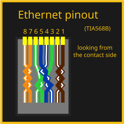
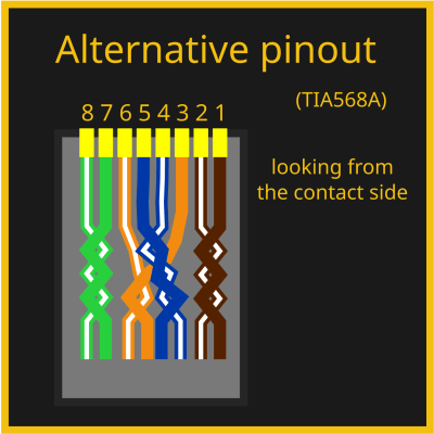
Of course, there are eight wires and eight pins, so you might be wondering – is there a mapping? The good news is – there is indeed! The bad news is – there are two of them. Fortunately, it’s easy to choose – the T568B mapping is the most commonly one used, with the T568A mapping being way less popular. Wikipedia tries to convince you that T568A is technically the best mapping ever, but you shouldn’t listen to it – a random cable in your cable box is way more likely to use T568B than T568A, and same goes for Ethernet cables worldwide.
You won’t need to learn the mapping, but if you want to, it will be all that easier as soon as you notice that the color and white wire pairs alternate. One quirk – the blue pair is in the connector center, which might feel counterintuitive. Here’s a fun fact, though – back in two-pair-utilizing 10/100Mbps days, this pair would sometimes be repurposed in offices, to carry a desk phone line alongside an Ethernet link to a worker’s desk within a single cable. You have to use the same mapping on both sides of the cable. However, in earlier days, there were cables where you had to use both mappings at different ends. Let’s take a small detour and learn about these cables, that you might just encounter if you work on really old tech.
Crossover
You might have heard of a thing called crossover cables. These were 10/100 MBps era Ethernet cables where the ends were crimped in two different ways, one in A variant and one in B variant – essentially, crossing RX and TX pairs. Direct (same pinout on both ends) mapping cables were used for switch-to-PC connections, and crossover cables could be used to connect two PCs or switches directly. Reason is, at the time, Ethernet expected you to cross RX and TX pairs ala UART, but ports on devices like switches would have them already crossed for convenience. Of course, this created a fair bit of problems at the time whenever you needed to rewire things.
However, for almost two decades now, crossover cables have been unnecessary, because every self-respecting Ethernet interface has adopted the technology called Auto-MDI-X – it lets you use both crossover and straight cables for connecting anything to anything, automatically detecting RX and TX and adjusting accordingly. You don’t need to bother with crossover cables nowadays, they have never been a thing for Gigabit Ethernet, and you’ll rarely ever find a piece of tech that doesn’t support Auto-MDI-X. If you want to learn more about crossover cables and tons of other Ethernet stuff, read here. It’s a still good thing to know exists in case you’re working with something seriously old that’s Ethernet-equipped, or if you stumble upon “crossover cable” as a term somewhere and wonder if you have a knowledge gap.
So Much More To Learn
We’ve covered pinouts, cabling and connectors, and that alone makes for a solid understanding of how Ethernet works at its core, at least as far as consumer tech is concerned. This is the surface-level of Ethernet, that you want to keep in mind as you hack on it further, and if you’ve had any knowledge gaps, hopefully this article has helped you cement your understanding. If you want to learn more in-depth, I’ve linked a couple articles inline – there’s never a shortage of Ethernet reading material online! Now, a lot of it is outdated or wrong, but the pages I’ve linked here, look pretty alright. Also, here on Hackaday, [Maya Posch] has written about Ethernet before in more depth – check her articles out!
There are so many more sides to Ethernet, however – physical level insights, microcontroller and SBC requirements, MII and GMII, MACs and PHYs, magnetics and magjacks, mediaconverters, Power over Ethernet, switch ICs, embedded Ethernet, and a good few more hacker bits and pieces. Next week, with the base knowledge in hand, we shall dive further!
Featured image: “10base-T” by [gratuit]


Bonus fact comment time! If you have crimped Ethernet cables before, especially the old kind of cables, you might have seen that different colour pairs have different twist rates. There’s two reasons for that, that I know of.
With CAT5 cables and CAT5e manufactured out of spec, it appears that quite a few cables barely twist the blue pair at all, I suppose because it wasn’t used in the 10/100Mpbs times..
Proper CAT5e tends to have all four pairs twisted properly! However, the twist rates between pairs are still different, though now it’s for a different reason and it’s harder to notice. Since the four pairs run alongside each other inside the cable, you have to have different twist rates to avoid twisted pairs interfering with each other – especially in cables where the pairs are not individually shielded, which is the overwhelming majority of them.
I would hazard a guess that they don’t twist the cable to cut cost as twisting increase the length of the cable.
Negative. It makes quite a difference electrically, and the twists help to prevent crosstalk (signals jumping pairs). I used to sell cable certification tools, starting from when they first reached the market. The Fluke DSP-100 would allow for live scanning of a cable while it was being manipulated – I’d take “badly crimped” cables with a lot of the outer jacket missing, and twist and untwist the pairs while the tool was scanning. You could see crosstalk levels changing in real time. That little demo in and of itself helped me sell quite a few testers.
Look above. The untwisted wires are not being used because at the time the cable is used for 100Mbps Ethernet.
What about this:
https://en.wikipedia.org/wiki/Twisted_pair
?
yeah, linked in right under the first diagram! it’s a good page ^~^
The 10BASE-T waveforms were carefully designed to minimize radiated emissions, and the dribers and receivers are matched to the 120 ohm impedance of CAT5 cable. Except in very noisy environments, shielded cable and connectors are unnecessary
10base-T is just Manchester encoding. It’s, uh, not really carefully anything.
And the impedance of all “Category” cables is 100 ohm, not 120.
Nominal. You are correct. I misremembered.
This i found interesting: ” 10Base-T1S employs the Differential Manchester Encoding (DME) method. DME is an example of a differential, bi-phase encoding technology specified in the IEEE 802.5 standard for Token Ring local area network (LAN) topology.
With DME, the clock is embedded and the data is sampled between the clocked edges. Because it lacks a DC component, this encoding scheme allows electrical connections easy galvanic isolation, ensuring the signal never remains at logic low or logic high for an extended period of time, allowing for versatility in a number of automotive applications.
In classic Manchester encoding, we see a digital modulation scheme where voltagetransitionsrather than voltagelevelsare used to represent 1’s and 0’s. In DME, only thepresence or absenceof a transition during the bit interval is important, not the polarity. The presence of a transition represents a logical 0, while the absence of a transition represents a logical 1. Whether the signal goes line-high or line-low depends simply on its state the previous bit interval, there is no need for reset transitions. This increases bit rate at lower bandwidths, because one bit is guaranteed to occur every interval. It also helps with data recovery in noisy environments, like automotive, because DME allows for a data stream to be inverted, yet still be properly decoded, unlike classic Manchester where the polarity is significant.”
At least for me, my first dive into Ethernet was actually my first introduction to signal encoding in general: and so when I first saw Manchester encoding and DME I was like “oh this is neat.” – it was being done in an FPGA so the output’s easy (you just xor with the clock) and decoding it is similarly simple.
Then you learn about the spectral qualities of the signal and you’re like “oh” and all that simplicity’s abandoned and you get Gigabit scrambled PAM-5 encoding that’s got a freaking 7+ bit ADC running at 125 MSa/s hidden inside the chip with active echo cancellation and baseline wander correction and you’re like “nvm.”
It’s hilarious because you get people who don’t know this who are surprised that 10/100 Ethernet runs at basically zero power and gigabit is a *massive* jump up, whereas if you know what’s going on under the hood, it’s incredibly obvious why.
The encoding is, as you say, Manchester. However the waveform *shape* – risetime and other characteristics were modified for the differential case of CATx cable, from the original single-ended shape used on coax. And, as Bruce mentions below, the drive impedance also changed. Much attention was paid to minimizing RF emissions from the unshielded cable.
Compare this to the case of Token Ring over twisted pair — there was no opportunity to mess with the waveform shape, because pulse width, risetime and jitter were all strictly specified. 16Mbit TR products were far more challenging than 100Mbit Ethernet products to get through EMC testing.
It’s entirely possible they *thought* of it as minimizing RF emissions, but it wasn’t – it’s really just minimizing loss and NEXT/FEXT, because you’re matching the signal to the characteristics of the cable (the impedance of the cable is not 100 ohms where it’s lossy, so slamming a signal with bandwidth content way above the cable into it will cause problems). Obviously when you have loss like that the energy has to go *somewhere* so yeah, it causes additional RF emissions. But Manchester is pretty darn bad in terms of spectral content anyway, since it’s higher frequency than required.
They *did* actually put thought into minimizing RF emissions for Gigabit and future Ethernet coding, which expressly whitens the data to help meet emissions testing (also helps NEXT/FEXT too, but not as much).
Stems from a paper that Clayton R. Paul published back in the ’80s. I think it was in the IEEE Trans on EMC or maybe an IEEE EMC SYmposium paper. By analysis he showed that if you took adjacent twisted pairs with a number of turns equal to N and M over the same length then the maximum crosstalk occurred when N=M and the minimum when N=M+1/2. Higher twist rates would be expected to produce lower crosstalk but since there is an accompanying modification of the characteristic impedance of the pair due to coupling between adjacent turns that also influenced the adjacent pair crosstalk. Generally it was determined that adjacent pairs should have different twist rates and a lot of effort went into the modeling of crosstalk in multi-pair cables.
John Benham – did you work at Chipcom/3Com?
Weird, I always found blue to be twisty, and brown to be the nearly untwisted pair.
2.5gb adapters and pcie cards are cheap, 5gb i havent seen much yet, but i asume aswell. 10gb cards are also not too expensive these days. Aliexpress knows some intel based ones that are really cheap because intel x540 is only capable of 100, 1000mb and 10gb, no 2.5 nor 5. But the x550 and such can and are therefor more expensive. But a dualport x540, get 2 (15 euro each atm) and you can have 10gb for 30euros. Not bad, sad about the compatibility. 2.5gb dongle for my framework was 14 euro, while the official one is 45 euro. But 100mbit for a embedded systems network would be fine enough.
I recently switched over to 2.5Gb network switches and PCIe cards. Seemed like the time to upgrade my internal home network from 1GB. Works great, not that expensive of an upgrade.
Good article.
With all the ‘wonderful’ Wi-fi out there, it may be time to look at hard wiring again. Just saw an article that burglars are starting to use cheap jammers to cut camera video while they do their thing. I personally try to hard wire everything I can on my home network. I have the end crimper tool and cable checker (not that expensive). More wiring, less convenient, but worth it. I go as far as having two separate networks. Home and Internet.
I totally agree with you. I personally have PoE cameras, and my PoE switch is protected by an UPS (as well as my video server). I modified my UPS to use two big truck batteries, and have +12 hours of power protection.
POE is usually the main reason. Security is a bonus. Other way is either powerline or Moca with the power adapter still needed.
same , but be aware quite a lot of UPS “boil” the battery with too high a charging voltage, solution is to hack the sence circuitry, or use a battery type that tolerates it (calcium ford batterys for example) .. I discovered this as regular flooded lead acid would get ruined after about 3 years use.
You are not alone, in my house also everything that has an Ethernet port is connected through it. The speed gain is notable, smart TV and CCTV cameras are the ones that show the greatest improvement in performance. Having dedicated routers for IoT and for cell phones and notebooks is also an excellent idea. Most people don’t make the most of 50% of their connection because the internal network is sloppy or outdated, this applies to companies too.
Longer distances can be covered by fiber optics, media converters can be purchased for negligible amounts.
I am utterly ignorant about networking. If I have one coax internet cable coming into the house, and it goes into my cable modem, how do I then set up multiple dedicated routers for different classes of devices?
I believe you connect that “router” to a fancy switch called a managed switch. This allows more options than a plug and play switch, for example to define a few ports belonging to one network and other ports to another, with rules on how devices on one network can (or can’t) send packets to devices outside their network.
While a full explanation isn’t possible here, you normally wouldn’t set up multiple dedicated routers. You would instead break up your network into “virtual LANs” (VLANs). The way to do this is to create separate VLANs for each category of devices you want to isolate from the others. You might have VLAN1 for your important devices like your PCs and servers. You’d set up another VLAN2 for your less trustworthy IoT things, like printers and TVs and refrigerators and water heaters, things that should never need to talk to your home PCs.
After you decide how you want to divide your network, you configure your network switch to assign specific VLANs to each of the ports in your switch. VLAN1 for the port where your PC is plugged in, VLAN2 for the port where your TV is plugged in, and so on. Also note that a decent access point will allow you to run multiple SSIDs, each assigned to the VLAN of your choosing. So you can configure your laptop to connect to “MySeriousNetwork” which joins it to VLAN1 so it can get to your file server, and your wireless toaster and bathroom scale to join “MyToyNetwork” assigned to VLAN2.
Next, you go to your router and set up the VLANs. You’ll first create a rule that denies traffic requests that originate from VLAN2 that want to talk to VLAN1. This keeps the toaster from accessing your file server. Then, you open only the deliberate ports that you have a need for. For example, you might have a home server on VLAN1 that also hosts your media on Plex, which listens on port 32400. On VLAN2, where your untrustworthy TV lives, you still want to watch movies from your Plex server. You then add a rule permitting port 32400 traffic to flow from VLAN2 to VLAN1. Your TV can now watch Plex, but nothing else.
So now if an attacker hacks your TV or your toaster and totally controls it, he can still only try to hack your Plex server on port 32400.
Of course there are an infinite variety of ways you can configure VLANs, and you can certainly go as deep as you need to. It really depends on your personal threat model (What risks are you concerned about? What kinds of attackers are likely to target you?) and that should help you determine how much effort and inconvenience you’re willing to put into protecting your stuff.
As said above there are many ways of approaching the problem of multi networks. I need only ‘two’ networks for my home setup so no need to get ‘fancy’.
I kept it ‘really’ simple. Rather than VLans and managed switches, I just added another Ethernet card to my PCs/devices. They are cheap. One for Internet access and the other for the home network. So the ‘cable modem’ connects to a WiFi-router -> switch -> one interface (could be hardwired or WiFi) on each device that needs internet access. Then the other interface to a separate wifi-Router and switches for those that don’t …. So networks are ‘separate’ physically and IP4 wise (say 199.168.0.0, and 174.40.0.0) . All automation projects, printers, servers, SBCs, and Micro-controllers on home network. Only desktops get 24×7 www and local home access via the two ethernet cards in each. Linux services that need no internet access are bound the home network card (like sshd, nfs, etc. ). And of course firewalls on the internet facing devices block as well. Laptops/cell phones with one interface are usually only on the www network, but can switch networks as needed. As for file server which has two cards, I physically ‘plug in’ to www switch when I want to get updates (which isn’t to often as it is not broke, so no need to fix). When done, I unplug, so never connected to www for extended period of time. Safer that way (I feel).
I should note that a WiFi Router usually has a 4 port switch built in which might be all you need. I needed more ports, so I added a 16 port switch (cable modem->switch->devices).
There are also different types of connectors for solid and stranded wires. Some are for stranded only, some are universal (not sure about “solid only” ones). Once our boss ordered some connectors that didn’t want to crimp properly, and would have trouble working. We later found out that they were for stranded wire only, and we crimped them on a solid one… a thing to watch out for.
The way an old radio tech taught me to identify them, is to look down the connector along the axis of the wire. If the teeth that bite into the wire are all in a straight line, it’s for stranded wire (when you crimp, they just push straight up into the center of the wire). If they are bent slightly to the side, alternating sides, it’s for solid wire (they’ll get pushed to either side of the wire, gripping it).
The opening in the connector for the cable can be different too, depending on whether it’s for “flat satin” (not sure the correct term, but think phone cord, but 8-conductor) or for a round Category cable. I tried to make sure I always stocked up on connectors that had the opening that worked for both (squared, but with a round notch at the top) and had teeth that worked on both styles of wire. Life was too short to spend it dealing with bad crimps, or digging through your bag trying to find the appropriate connector that would actually slide over the cable jacket.
As a small “interconnect” vendor in the ’80s-’90s, now retired, I installed a lot of both telephone and Cat5 data cabling; at Graybar Electric I found some interesting 8p8c connectors; they were made to accomdate both round and flat cable, stranded or solid, and were made narrow to fit either 6p6c “RJ11” or 8p8c “RJ45” jacks, and were certified for Cat5. They could be installed by a standard 8p crimping tool They had a blue tinted body and IIRC were made by Siemon. They were a little pricey, but I liked only having to stock one type of connector, and found them easy to install and dependable in use.
Anyone ever try to communicate directly with an Ethernet Chip from a microcontroller?
i.e. without an operating system and associated network stack?
we have covered quite a few hacks like that, indeed :3
Thank you, Arya!
I discovered a board called a RP2040_ETH, it has a very interesting chip the CH9120. It’s a pretty much direct ethernet to serial bridge that requires very little in the way of supporting components beyond a crystal and a few caps. Unfortunatley it didn’t meet my requirements so I haven’t personally played with it, but it looks like a very easy way to get basic comms up and running fast.
I ended up with a WT32_ETH01 board which worked very well for my purposes (artnet), but there’s also loads of ethernet modules you can buy that use an SPI interface.
Thank you, A!
Not sure if I’d want to use standard ethernet connectors in an automotive application due to vibration. I wonder what they use instead?
https://www.teledynelecroy.com/doc/10base-t1s-auto-ethernet-tech-brief
stuff like this, apparently!
I’m still waiting for it to become widespread and cheap enough for diy tinkering. Networking aside, that would be quite interesting also for interfacing other things, say lab equipment or musical instruments (MIDI over SPE in live situations would be absolutely killer).
The closest equivalent to Ethernet in an automotive application is the CAN bus or some variation of it.
To my knowledge, each automotive manufacturer uses their own proprietary connectors. Communication is typically done through an OBD (Onboard Diagnostics) connector, utilizing a scan tool. There are both generic OBD cables and software, as well as manufacturer-specific cables and software.
I have personally never seen an RJ45 connector used in an automotive application. I’m not saying it doesn’t exist, just that it’s not common.
The closest thing to Ethernet in an automotive application is Automotive Ethernet
You can get plastic clips that lock into place under the tab and you need to use a tool to release them, they’d work for vibration resistance too but ideally I’d choose an automotive rated connector.
Alternatively I’ve also used plug/socket combos which have a kind of bayonet lock and are IP rated for outdoor use (expensive)
M12 connectors are used for industrial ethernet
☠️The 1-to-2 Ethernet splitters are actually very practical. But for some reasons, most of the EJ45 splitters on eBay are of the useless type that mirrors all the wires, like audio splitters. It is almost always a disaster waiting to happen. With many devices nowadays have Ethernet on standby even in the “OFF” position, those splitters are practically useless. The GigE-to-2-FastE splitters should cost the same to make and they are SO much more useful.
I made a few of these wires myself, with the best being one cable with 3 connectors on each end (two POTS phone lines using one pair each and two pairs for one 100MB connection). All my friends seeing my modem were appalled by this, except for the one that actually is a professional network engineer, who liked it.
> These were 10/100 MBps era Ethernet cables where the ends were crimped in two different ways, one in A variant and one in B variant …
Nope. If you do that you wont get any 100Base-TX connection at all.
100Base-TX uses PINS 1+2 & 3+6 but when you crimp one end “A” ant the other “B” pins 1+2 will still be connected straight through and the other (two) pair(s) will have one end connected and the other floating.
As in “A”+”B” is equal to crossing pins 3+6 with 4+5 but 1+2 remain untouched.
DOH, forget what I wrote – dunno what happened but The A/B graphics here must’ve confused me into thinking pairs 3+6 vs 4+5 were switched instead of the correct ones 1+2 vs. 3+6. *shakeshead*
In my old days as a telecom.and network vendor, vendor, to make a true cross-over cord I transposed ALL 4 pairs, even though only two pairs were ever used, and I never bundled voice paths onto data cabling. It’s not a “true” crossover if you don’t transpose all 4 and there were some telecom applications that used 4 pair wiring, such as those gosh-awful Merlin systems.
Jeah – stumbled over that “problem” myself: Buying a ready made crossover cable only to find out only two pairs were flipped.
Had to re-crimp a few cables to get them working how I wanted them to: Transmitting 2xN inter-switch “trunking” connections on a few LAN parties over N cables.
And at least one or two of the first few 19″ switches with GBit uplinks I had weren’t quite able to negotiate a (stable) 1000Base-T connection between each other. Dunno if it was related to a half/full crossover cable, failing auto MDI-X negotiation, bandwidth negotiation or a some combination but when I forced one end to 1000Base-T (instead of auto negotiation) it worked.
My memory is hazy but yes, just transpose it all, easiest to remember and easy to spot through transparent connectors. After so many years…decades, away from it, it’s nice to learn that transceivers have been agile for a while.
I’m a bit confused about “looking from the contact side” on the pinout diagrams.
Is it supposed to show the “bottom” of the plug, with the locking tab being on the opposite side of the plug from the side that is being shown?
yes, it’s the “bottom” of the plug indeed! I should’ve added a view from the end too, come to think of it.
Ok, but if it’s showing the bottom of the plug (as if I’m holding the cable in my hand, pointing upwards, looking at the contacts on the plug, locking tab away from me), then the pinout shown should be mirrored?
T568A is overwhelmingly used as the default here in New Zealand, and I would hazard a guess that it’s the same over the ditch in Australia too.
I believe the main reason that the T568B standard was so popular in the US was because it matched what AT&T used in their Merlin key telephone system, which actually predated twisted pair Ethernet cabling. Not being a Merlin Vendor, on new installations I used the TIA recommended T568A pair assignments; either works fine.
568A matches telephone wiring colors on the first two pairs (BLU and ORG) so it’s compatible with any existing telephone use. Everything pre-wired (jack panels, etc) I have is wired 568B
It’s a color code only thing. As far as jumper cables are concerned, it doesn’t matter. The wiring is the same in both cases except that GRN and ORG pairs are swapped. If you ignore the colors, the same pins on each end are connected in both A & B standards.
Another major benefit of Ethernet: galvanic isolation is commonplace and relatively simple to implement. This is not true for something like USB.
Galvanic isolation is not just commonplace, it’s an intrinsic part of the specification since 10B2, any Ethernet device that doesn’t have it does not meet spec (even if it still works) and could possibly even be dangerous in the event of an electrical fault.
Our IT guy has gone crazy with 5GBit and 10Gbit links in copper, expecting every link to hit advertised max speed (which they never do), but with fiber interfaces getting cheap and easy to source, I’m confused as to why he didn’t use them instead. Anyone have insight into that?
10G over twisted pair also uses a lot more power than fiber. It’s not much of an issue with a couple of ports, but when you have a rack full, you need a lot more cooling and a larger UPS.
The older Intel cards that are super cheap on ebay now use about 10 watts per port for twisted pair.
Crimping your own ethernet cables is relatively easy, but terminating fibre is a bit more tricky, and requires more specialist equipment. So you either have to buy pre-made fibre and hope that you can lay it without damaging it, or hire someone to run it and terminate it.
Basically, running copper is easier and cheaper.
Take it from a pro. Do not use the pass-thru RJ45s. Blade for the tool wears out quickly and the cheap tools don’t cut flush enough and causes other pairs to short.
Also those splitters that break out a single ethernet cable into two you will need two of them on each end of the main run.. I run into this all the time. Some one buys one to split their ethernet drop in their home office so a laptop and printer can share but doesn’t work. Duh, you need it on the other end as well. However it turns a warranty call into a service call so I can’t complain too much.
It really annoys me when people get those splitters instead of a proper switch
I get it that they might not know what a switch is but I really hate that these products even exist in the first place as most people tend to search for “splitter” and get these products that don’t work as the general expectation of how they should work
Tool blades are a consumable. I prefer the feed-through ones because it’s easier to get the parallel section in the plug as short as possible, which is especially important for cat6.
I don’t even see any advantage to using the passthrough plugs. Once you’ve crimped a few, you will be able to cut the wire to the right length without even measuring.
Note to self. Must stop using ethernet over coax because apparently its slow and I’m only using it for nostalgic reasons.
Glad I’m been informed how I’m doing it wrong. Must also re evaluate the use of two wire ethernet which also likely no longer has practical purpose.
Possibly you could put SMA connectors on your coax and run ‘wireless’ over it by plugging each end into the antenna port of a wireless card.
I suspect he’s referring to twinax
Tried that for giggles, but essentially two wire Ethernet “is a thing” and then running over existing coax is also a thing & long distances too::
https://www.realtek.com/en/products/connected-media-ics/item/rtl8201g-i-vb-cg
But twinax – different beastie.
Some of us remember the days of the old DEC Delni ethernet coax tap. The coax used for the trunk ethernet connection was so stiff and the Delni module so light that a brick was required to weight it down and keep it from going wherever the coax told it to go.
Oh, where to start:
@Bruce Gettel: DING DING DING! minimizing crosstalk is the reason for the varied twist rates; Crosstalk means CRC errors, dropped packets, and other assorted badness.
@Lee: PLUS MANY. I can’t STAND that type of connector. My go to are the Amp / Tyco 8p8c connectors, mostly because I have a Crimpmaster die expressly for that style plug. (the ones that Ideal sells at the Home Improvement Box stores are a ‘good enough’ clone of them.)
Some assorted rambling about ethernet, termination tools, and other networking shenanigans:
Another reason to use a proper crimp tool (even the “cheap” squeezy ones) are to lock the cable to the plug- that is also the reason why you MUST put the out cable sheath in the plug, and in far enough to allow the plug’s plastic nubbie to lock in the cable for some limited strain relief. I used to be an installer and still make my own patch cables and other networking shenanigans, and my go to crimp tool was an Ideal Crimpmaster handle, and an RJ-45 (or RJ-11) die. As long as you get the conductors in the right spots, it’s pretty much a guaranteed good crimp on two cycles of the tool. The frame part of the tool ain’t cheap, usually around $75 USD, and dies running anywhere between $30-$50; It’s usually a good deal to find a frame that comes with the die you are most likely to be using in it.
on test equipment:
the cheap pair testers… are pretty meh, really- all they do is test to see if the pairs have continuity. Get something that does individual pins, or if you want to get really fancy (and have the cash to spring for it) get a NetScout or something that does a bunch of cool stuff, like tell you if it’s a live port, and if the switch supports it, what port you’ve connected to. The company that made my tester got bought out by Black Box at some point in the distant past and then discontinued, so I can’t really recommend it, but for what I paid for it back in 2000, it was pretty feature packed. (individual conductor, the ability to use multiple remotes, and cable length via capacitance all in one tidy package.) The current equivalent would be a Scout Pro 3 from Klein Tools, at least for feature set.
re: ethernet splitters
While I’m loath to throw two runs of ethernet down a single cable with those splitter devices, I have pulled those shenanigans in the past for one-off things.
A ‘quick n dirty’ cross over cable can, in fact, be done by doing a 568A for one end and 568B on the other, while a proper TX4 crossover swaps the brown and green pairs as well.
on performing additions to an existing site, or terminating an entire site:
For the love of Bog, use ONE termination style- Usually 568B is the most popular, but if you are adding to existing cabling infrastructure and it’s using 568A, then make yours match. I knew a guy that did their own thing (we called it 568D) but at least the guy was consistent about being wrong with it, and at the end of the day, that (along with the test results!) are what matters. Be kind to the poor sod who comes in after you have moved on to a better paying contract and has to deal with your work- are they going to be referencing chapters out of the Book of the Profane cursing you and your family for the next seven generations, or are they going to go “That was good, solid work right there.” I will admit to doing jobs that made people coming in after me do both. (not the same job, though…)
568D – sounds like what I had been known to do on occasion in the early 2000’s. I’ve had entire spools of cable where getting green next to orange is like wrestling a lion, and no amount of tricks developed throughout the years seem to be able to win against that foe. (It seems we all develop the same tricks as I have watched numerous people who never watched a youtube video, just picked up a crimp tool in the 90’s and got to work, use the same tricks as I have come up with!) Since none of these spools were ever permanently run anywhere, and they were for patch cords in the house, I just said screw it, and split the blue pair between 3 and 6 rather than the green. Because of that, to this day, despite not having had any of those spools in a very long time, if I reterminate a cable, I check to see which pair is used :)
Quibble: ethernet was originally not about point-to-point connection. Instead, it was a shared antenna on which many devices could be connected to transmit and receive, with particles for preventing and handling simultaneous attempts to transmit. In fact, an ethernet subset known as Chaosnet eliminated the predictive part of that entirely, and relied entirely on checksums to detect garbled packets, waiting for random delays before retrying them to try to keep repeated collisions from happening. (I spent some time maintaining a set of chaosnet drivers in a surprisingly small amount of PDP11 assembler code.)
The ability to run without a central switch or router was, in fact, one of ethernet’s advantages over other networking technologies of the time. In many ways, it came closer to being a serial bus than what we now consider common ethernet connections, with individual devices checking incoming addresses to decide whether they should respond.
That changed when ethernet was moved from coaxial cable to telephone style “Base T” twisted pair, and when dara rates increased. But it’s worth remembering that the “ether” in Ethernet refers to the radio-like broadcast communication layer at the lowest level.
(One can quibble about whether point to point twisted pair with switchers is Ethernet at all, at the hardware level. But it’s still using Ethernet packet protocols, I believe, so it isn’t unjustifiable.)
Aloha, and well said! (Saved me some typing too)
Typo: s/particles/protocols/.
5Gbs and 10Gbs ‘on the horizon’?
That’s a bit out-of-date…
I’ve had a low-cost Zyxel switch with 10GbE RJ45s for a year or so now, and my Mikrotik switches (CRS305s and CRS309s) have a couple of 10GbE RJ45 SFP+ modules in them – along with a bunch of fibre SFP+ modules (I put in 6 core fibres between rooms at home instead of Cat 6 and use two of those cores for 10Gbs fibre backbone connections between rooms).
Article probably should have mentioned the new “single pair” Ethernet specs.
Take a look at 802.3cg standard. Ethernet might soon become the last fieldbus you will ever need! Perfect for IoT. Also known as 10BASE-T1S
> “Not a good crimp”
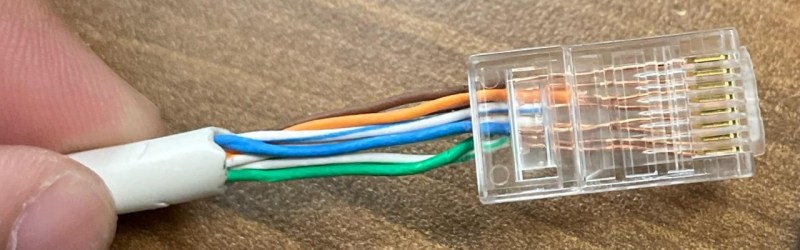
A friend asked me to help him install the GB ethernet in his new house (he is a professional video editor and used to be a semiprofessional theatre lighting rigger in the ’90s, so he knew how to correctly mount a power or XLR cable to their plugs). He had fortunately ran all the cables already, but he had trouble getting the RJ45 (yeahyeah, 8p8c) plugs installed on the cable.
When I arrived at his house he had stripped all cables painstakingly like in that image, which had taken him more than 2 hours for just 6 cables (12 ends). He looked so sad when the first thing I did was *snip snip* cut all those neatly trimmed ends off.
This was also the first time I encountered the plastic “x” shaped thing that keeps the four pairs apart. However, I’ve seen both cat6(a) cables with and without. What exactly is it for and is it a characteristic of certain cable types (i.e. is a cat6a cable without one out of 6a spec?) and how far from the plug are you supposed to trim it?
It’s a divider to further reduce crosstalk between the pairs. GB speeds shouldn’t need it but it CAT6 is rated for 10G. Ideally you should trim it to just behind the plug but again it isn’t really required for 1G speeds so don’t stress about it. As for the cables that don’t have it, they could just be made more precisely in other ways to hit the signal loss targets without the divider. But bear in mind that a lot of cables don’t actually meet their advertised specification for the full 100 meters that they are supposed to. If you do a 10 or 20 meter run with a cheaper “CAT6” cable it will probably work fine even if the cable should actually only be rated CAT5.
Thx!
There’s room for a part-2 here – all things PoE. There’s plenty of devices in use whose implementations of PoE predate and contradict the standards. And if you’ve got any cables that play around with switching which pair goes where, you’re going to need to figure out what you actually have on the other end.
Clip down
Orangewhite-orange
Greenwhite-blue
Bluewhite-green
Brownwhite-brown
Sing it with me!
Nice summary. In the ’90s and early 00’s I also sometimes encountered the USOC pinout, in addition to 568A/B. I think it was used for telephone systems. I have not see it much in the last 20 years, but worth mentioning in case it helps someone else.
Yep, bad crimping tools are a PITA. I have a crimping tool with swappable dies. I have an Ethernet die for it, but any cable I made with that would not work. I looked at the crimped connector through a magnifier, and found that some of the pins were not pressed in all the way.
The TIA-568 pinout numbering appears to be backwards in the HAD images, or am I missing something ?
( hadimg_ethernet_intro_8{a,b}.png )
Can anyone recommend a good, inexpensive RJ45 crimping tool?
We can thank Bob for inventing Ethernet.
https://en.wikipedia.org/wiki/Robert_Metcalfe
I like a leatherman multitool. Is version for survival, for electric man and why notbody create versionw ith ethernet press for making socket ethernet or meybe rj12 not only rj45
this is very similar device.
WHY?
Thinks for sharing Basics network things, i am curious why RJ45 called RJ45?