3D Printing On A Spinning Rod

FDM 3D printing traditionally operates on a layer-by-layer basis, using a flat bed to construct parts. However, [Humphrey Wittingtonsworth IV] demonstrates in his video how this process can be significantly enhanced in terms of mechanical strength and print speed by experimenting with printing on a rotating rod instead of the standard flat bed.

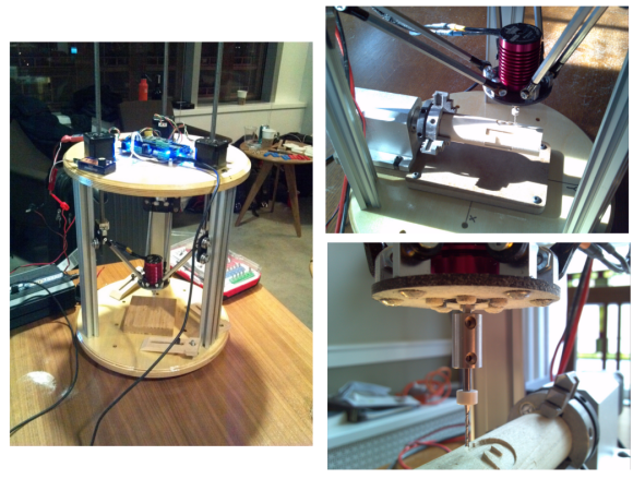
[Humphrey] modified a Creality CR-10 3D printer by removing the bed and installing a regular 8mm linear rod under the hotend. The rod is rotated by a stepper motor with a 3:1 belt drive. This lets him use the rod as the printing surface, laying down layers axially along the length of an object. This means parts that can stand up to bending forces much better than their upright-printed counterparts.

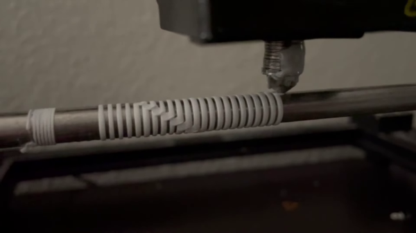
Additionally, this rotational action allows for printing functional coil and wave springs – even multi-layer ones – something that’s not exactly feasible with your run-of-the-mill printer. It can also create super smooth and precise threads as the print head follows their path. As an added bonus – it could also speed up your printing process as you’re just spinning a slim rod instead of slinging around an entire bed. So cylindrical parts like tubes and discs could be printed almost as quickly as your hotend can melt filament.

Of course, this approach isn’t without its challenges. It works best for cylindrical components and there’s a limit to how small you can go with inner diameters based on your chosen rod size. Then there’s also the task of freeing your prints from their rod once they’re finished. [Humphrey] addressed this by creating mesh sleeves that snugly fit over his center rod. This limits how much melted plastic can adhere to it, making removal a breeze.

Continue reading “3D Printing On A Spinning Rod”

RotBot Adds A Extra Dimension To 3D Printing, With A Twist

It always seemed to us that the Z-axis on a 3D printer, or pretty much any CNC machine for that matter, is criminally underused. To have the X- and Y-axes working together to make smooth planar motions while the Z-axis just sits there waiting for its big moment, which ends up just moving the print head and the bed another fraction of a millimeter from each other just doesn’t seem fair. Can’t the Z-axis have a little more fun?

Of course it can, and while non-planar 3D printing is nothing new, [Stefan] over at CNC Kitchen shows us a literal twist on the concept with this four-axis non-planar printer. For obvious reasons, it’s called the “RotBot,” and it comes via the Zurich University of Applied Sciences, where [Michael Wüthrich] and colleagues have been experimenting with different slicing strategies to make overhang printing more manageable. The hardware side of things is actually pretty intuitive, especially if you’ve ever seen an industrial waterjet cutter in action. They modified a Prusa printer by adding a rotating extension to the print head, putting the nozzle at a 45° angle to the print bed. A slip ring connects the heater and fan and allows the head to rotate 360°, with the extruder living above the swiveling head.

On the software side, the Zurich team came up with some clever workarounds to make conical slicing work using off-the-shelf slicers. As [Stefan] explains, the team used a “pre-deformation” step to warp the model and trick the slicer into generating the conical G-code. The G-code is then back-transformed in exactly the opposite process as pre-deformation before being fed to the printer. The transformation steps are done with a bit of Python code, and the results are pretty neat. Watching the four axes all work together simultaneously is quite satisfying, as are the huge overhangs with no visible means of support.

The academic paper on this is probably worth a read, and thankfully, the code for everything is all open-sourced. We’re interested to see if this catches on with the community.

Continue reading “RotBot Adds A Extra Dimension To 3D Printing, With A Twist”

4 Axis Delta Router Says Hello World

deltaRouter

[Bart] stood upon the shoulders of the delta 3D printer giants and created this 4 axis delta router. The router was originally created for ORD Camp, an invite only hackers gathering. Each year he creates a new thing with one main purpose: to spark conversation. In his own words “Practicality and suitability are way down the list, so go ahead and snark away. If you do, you are missing the point.”

[Bart] did things a bit differently with his delta. For motors, he went with non captive steppers. “Non captive” means that rather than a shaft, the motor has a hollow threaded nut which rotates. A lead screw (usually with an acme thread) is passed through this nut. As the motor’s nut turns, the screw is pushed or pulled through the motor, creating a linear actuator. The only major downside is that a non captive stepper motor can’t be adjusted by hand. The screw doesn’t turn and neither do any external parts of the motor. For structure, the router uses MakerSlide and v-grove wheels. The spindle is a simple brushless hobby motor and 30 amp speed control. Rather than the outrunner motors we’ve seen lately, [Bart] wisely chose an inrunner motor normally used on R/C cars. Inrunners generally have less torque than their outrunner counterparts, but they make up for this in RPM. [Bart’s] motor is capable of 30,000 RPM, which is plenty for spindle duty. We think the motor bearings will probably need an upgrade, as the original motor bearings weren’t designed for side loads. For a controller, [Bart] utilized an  Azteeg X3 running Repetier.

The router made a great showing at camp, and [Bart] decided it needed a 4th axis. He sourced a rotary axis from eBay. To keep the software simple, he connected the rotary axis to the extruder outputs on his controller. He was then able to hack the mach3 wrapped rotary post processor to output extruder commands. The results look great. [Bart] says the system definitely needs a tailstock, and we agree. We’re looking forward to the next update on this machine!

Continue reading “4 Axis Delta Router Says Hello World”