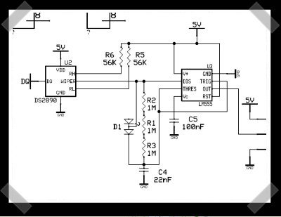
This is sort of a follow up to the diy A/C zone control post. It’s a pretty simple circuit, but now they’ve posted schematics for building your own 1-wire controlled servo actuators. It requires external power – so they’re supplying 15v via cat-5/RJ-45s. This isn’t limited to home automation, this could lead to some interesting 1-wire robotics projects.
16 thoughts on “1-wire Servo Controller”
Leave a Reply
Please be kind and respectful to help make the comments section excellent. (Comment Policy)


Interesting approach. Probably good for a bench test but why use all those parts when you could easily use a 6/8 pin microcontroller and call it a day.
w0oT first post!
As far as I see it this is just a simple adaptation of the popular 555 pwm configuration. And already the image on hack a day reveals a design mistake. The upper diode is unconnected!
but what is much worse is that they use a 7805 to power the servo and waste 10 V of their original 15 V. Where is the switching or pwm supply? Another one of the 555 pwm circuits could easily provide them with 5 V with 90% efficiency.
They don’t need the upper diode connected; they probably just had a dual diode package available, so used it. I did the same thing in one of my recent designs; I could actually get the dual diode SOT-23 package cheaper than single diodes.
Agreed on other points though; using a regulator like that is a horrendous waste; any of the CMOS 555 variants could handle the 15V supply all on their lonesome, and with a little work they could get the 5V-only Dallas part to work. Still, overall, a decent hack and an excellent starting point.
The biggest problem with the “single-wire” interface? It won’t be so easy to make it single wire!
Maxim is supplying the DS2890 (their only single-wire digipot) to current customers of the part only, so the chance of hobbyists getting a hold of new stock are nil… time to search the junk box and eBay. I’m currently looking for a similar part, but so far no luck (maybe something will turn up in the next 5-10 minutes).
if you can’t find the 1-wire pot, use a standard SPI or I2C pot and a PIC and emulate the 1-wire protocol. :-)
how about just sending the pwm to the servo over the line, instead of 1-wire serial, and do the interfacing at the source? makes more sense to me.
oh wait, the idea is to control many servos from one serial line? perhaps I didn’t read enough first… ;)
akmixdown: At that point why not throw away the 555 and pot and just use a tiny (10Fxxx) PIC to generate pwm from an input 1 wire bus. Extra points for using a PIC model with a comparator for stall sensing and reporting up the 1 wire.
pokey: now you’re getting the idea… :-) Creeping featurism
hackaday,
this is one of your lamest posts yet! I don’t like to flame but this post deserves it. the link provides no explanation of wtf the circuit does, and worse, it has the condescending remarks “if you don’t know, we’re not going to tell you, you’ll have to wait.”
Gordon aka justDIY
justdiy how about you stick to your namesake… LOOK at the damn circuit, it replaces a standard potentiometer with an electronic one. That’s it.
Honestly… if you don’t like it… feel free to start up justdiy-a-day. Bitching about it like a whiny 8 year old doesn’t get you anything.
The DS2890 is definitely available to DIYers. It’s readily available for a reasonable price at digikey. If you don’t know about digikey/mouser/the real distributors, you better start–I’d be willing to bet that most of the parts you had considered “unobtainable” are readily available through them.
A couple of notes: “1-wire” doesn’t really mean one wire. As you should probably know by now, you still need a return for the signal. The protocol is built-in the chips and is designed to work easily for many devices at once, however, so it still does have some advantages to some of the more traditional serial interfaces.
It also won’t be very easy to implement directly on a PIC; IIRC, there’s a lot of features in it, including inherent noise immunity, ability to address many different devices with builtin serial addresses, stuff like that–don’t take my word for it, I don’t remember all the details, so you can read up on the 1-wire protocol here: http://www.maxim-ic.com/products/1-wire/
Looking at the site, I just remembered/noticed something rather useful about the 1-wire chips: they can be parasitically powered from the data bus. That means you can power the 1-wire chip directly from the data bus, power the 555 from +15V, and drop the 7805 regulator entirely.
Speaking of switching or pwm power supplies. I have a project that would benefit from some thing like this. My requirements are simple. I need it to output a stable 5v to run a pic and a 2×16 lcd with led back light. In put is 6v so I need to lose 1 volt.
Any ideas?
perhaps a low-dropout regulator. google it, there’s gotta be some type that allows a voltage difference of less than 1V.
have a diy servo controller that controls up to 25 pics and a 2 wire output i made it for under $4 thats cheeper than the 555 and i can suffer one extra pin for price cheepernessisty
PS for post 2 it sometimes not a matter of price but what you have at your disposal
(the dual diode thing)