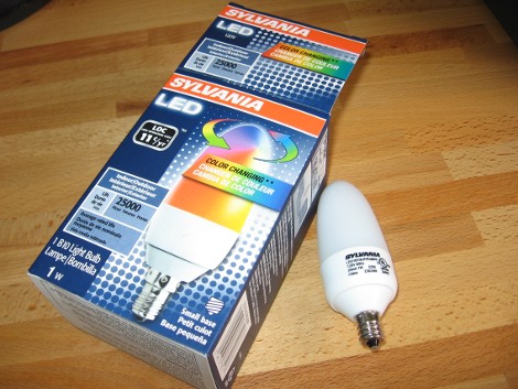
I went to the last monthly meeting of Sector 67, a hackerspace in Madison, WI. One of the things shown off was a color changing LED light bulb that Menards was clearing out for $1.99. Inside there’s two RGB LEDs controlled by an ATtiny13 and powered by an AC/DC buck converter. An ATtiny13 will run you around $1.25 by itself so this price is quite amazing. I grabbed a couple of these bulbs and set to work on them. Join me after the break to see what I’ve got so far.
Update: read a follow-up to this post.
These bulbs use a candelabra base so I grabbed an adapter and tried it out in a lamp. Here’s the result, you can see it stepping through color levels a few times a second:
[youtube=http://www.youtube.com/watch?v=yRrYp3qRBXc&w=470]
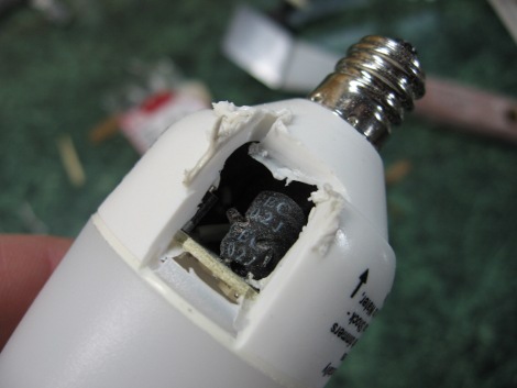
We’ve seen this in a lot of mood light hacks, I want to get at the hardware and make it do my bidding. First thing’s first, time to crack it open. For some reason I thought that carefully drilling some holes around the base would help me figure out where best to use the Dremel cutting wheel. Unfortunately I immediately drilled through one of the inductor coils. Drat.

Well, no stopping now. I’m not too worried as I also bought a solid red version of this bulb. I want to see what’s inside, whether it’s the same design with unpopulated components, or the full shebang with different hardware. I assume there’s no microcontroller inside so I’ll steal the inductor from that one later.
I cut off the diffuser and got to the circuit board. Here’s some images (click for hi-res) as well as a cursory list of hardware.
Top:
- R2 – 1004
- R3 – 1004
- R4 – 3001
- R5 – 1302
- R10 – 1003
- D4 – Looks like a zener… perhaps to set down votage for the tiny13
- D5 – RGB LED
- D6 – RGB LED
- D7 – JF S1J
- IC5 – ATtiny13
- C1 – smd without label
- C7- smd without label
Bottom:
- R1 – inline with center conductor of light socket
- P1 & P2 – Labels for incoming AC power?
- L1 – 102J CEC
- L2 – 102J CEC
- C2 – 50V 22 uF electrolytic
- C3 – 400V 4.7 uF electrolytic
- C4 – 400V 4.7 uF electrolytic
- C5 – 25V 100 uF electrolytic
- C6 – smd without label
- D3 – R106 TF
- R6 – 1201
- R7 – 1Bx
- R8 – 270
- R9 – 270
- IC1 – NGS (transistor for driving LEDs?)
- IC2 – NGS (transistor for driving LEDs?)
- IC3 – NGS (transistor for driving LEDs?)
- IC4 – LNK304GN AC/DC switching converter
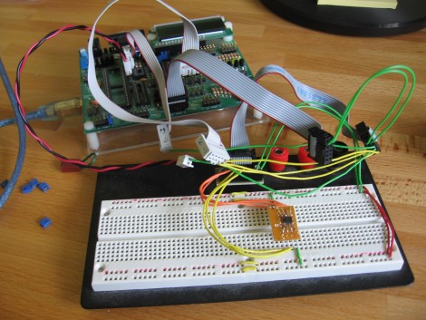
I wanted to see if I could talk to the ATtiny13 so I soldered wires onto the pins and hooked it up to my AVR Dragon programmer. ISP was a no go so I soldered more wire to the remaining connection and gave high voltage programming a shot. That was also a failure. But since I already hosed that inductor I have no issue popping the microprocessor off of the board. Here it is soldered onto some perfboard and inserted in a breadboard:

I tried ISP again and that was a no-go. But this time around High Voltage Serial Programming worked. I talked to the chip with AVRdude using this command:
avrdude -P usb -p t13 -c dragon_hvsp -v
That polls the chip and reads back the fuse settings. Currently the lfuse is 0x6A which is the factory default but the hfuse is 0xFA. After checking the datasheet I see that they’ve disabled the reset function (that’s why ISP doesn’t work) and enabled brownout detection. I dumped the firmware and the eeprom and that’s where I’m at. Now I need your help.
I haven’t done much reverse engineering before this so I’m not sure what to do next. I disassembled the firmware using ‘ndisasm’ but I have no idea what I can learn from it, or even how to read it. I’d love some help answering two questions:
1) Why couldn’t I talk to the chip when it was on the circuit board?
2) What can I learn from the disassembled code. Update: after running the code through an AVR disassembler it looks like this is just an ascending list of numbers. [Tiago] pointed out in the comments that this is the behavior when the lock bits have been set. It should be possible to reuse the chip by erasing it but I won’t be able to dump the firmware first. Now I’ll focus on figuring out how the board is routed.
Let me know in the comments.


I’m just a normal boy doing a google search and got to this page. My jaw is dropped knowing there are people in the world computer hacking a light bulb. An effing LIGHT BULB! I don’t understand a sentence of how you explained it, but I’m glad to know there are brains in this world. Thank you for giving me hope for the human race.