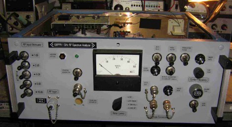
This spectrum analyzer project seeks to improve the quality of tools available to amateur radio operators. A lot of thought has gone into the design, and those details are shared in the verbose project log. The case was originally a CATV link transmitter, but most of the controls seen above have been added for this build, with unused holes filled and finished to achieve the clean look.
One noteworthy part of the build is the time that went into building a rather complicated-looking 1013.3 MHz cavity bandpass filter. Despite the effort, the filter didn’t work. Details are a bit sketchy but it seems that some additional tuning brought it within spec to complete that portion of the device.
This certainly makes other toy spectrum analyzers look like… toys.
[Thanks William]


Wow, this is serious stuff.. and well documented.
The “serious” page has a link to the “toy” IM-Me spectrum analyzer. ;-)
And here’s a $10 spectrum analyzer made from a 555 timer IC, that connects between your communications receiver IF signal and an oscilloscope:
http://www.qsl.net/n9zia/spec/Homebrew_Spectrum_Analyzer.pdf
This page is worth visiting just for the bibliography. It is a very good survey of both analog and digital homebrew spectrum analyzer techniques.
@Rob Wentworth
Well played. Though, good luck making measurements with it :)
Also, I know something about the 1013 Mhz cavity filter (I’m working on my own build of the “Scotty Spectrum analyzer” http://alternet.us.com/?page_id=751 )
The plumbing pipe cavity filter he built probably didn’t work because the “hairpin couplers” between cavities look like they’re too far away from the sides. They’re really only supposed to be about half the width of the insulators away. He had an aluminum cavity filter machined from the designs of another spectrum analyzer, which did work. It looks like it shouldn’t be too much trouble to make it at home if you have a drill press, though.
Very nice build, and quite educational!
A bit off-topic: does anyone know what’s the software used for drawing block diagrams for RF? Something like the one in this project or like the numerous ones in ARRL or datasheets.
nice, but I think WA7MLH’s update of the old W7ZOI design has it beat.
http://www.neoanderthal.com/wa7mlh1.html
2/3 of the way down
The thing I like about “scotty’s spectrum analyzer” is that it takes the oscilloscope out of the equation. It’s nice to have everything on the computer, so capturing plots and taking measurements is stupid simple.
http://scottyspectrumanalyzer.com/
It’s also worth mentioning that the scotty spectrum analyzer is having a PCB group buy right now, so jump on the mailing list if you’re interested.
http://groups.yahoo.com/group/spectrumanalyzer/
Ah yes, the GBPPR, quite an interesting site to rummage around at. There are loads of other interesting projects and ideas there. If you’ve never gone to the site, you could spend hours reading various pages. Just one fyi, just ignore the pages/part of pages that are political :( .
Some day I’ll Start the spectrum analyzer project, but I should complete my poor person’s service monitor first
Hey – if you guys are interested I have built an spectrum analyser using an Arduino and Pi to an OLED display for audio. Check this out! And get in touch bearaudio.blog/2017/09/08/mvista-predac-spectrum-analyser/