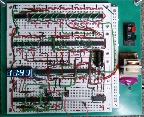
One afternoon, [Sam] was a bit bored and decided he would build a clock. Not wanting to spend any money on the project, he set off to construct his clock using only the components he had on hand – this meant no micro controllers would be used whatsoever.
Built on a set of four breadboards, his clock sports a pretty short parts list. It uses just over a dozen flipflops, a few NAND chips, a 555 timer, and a small handful of other components. What you won’t find on the bill of materials however, is any sort of crystal or real-time clock. Instead of using a separate chip for keeping time, he opted to use the 60hz mains frequency as the basis for his time keeping.
The mains sine wave is passed through a series of frequency dividers to reach a 1/60hz signal, which is used to trigger the clock counters he constructed. The time is displayed on a 4-digit seven segment display, using a pair of multiplexers clocked by a 555 timer.
The clock seems to work nicely, though you have to be pretty well-versed in how the clock was built to set the time. The only means of doing so is to probe into the clock of the digit you are setting while pressing the lone pushbutton mounted on the breadboard.
While we are pretty sure no one will ever mess with his clock’s time, we have to wonder if it blinks on and off like our old VCR when the power goes out.


This is a piece of art!
Or you could bypass a frequency divider to step the clock faster to set time.
“using only the components he had on hand – this meant no micro controllers would be used whatsoever.”
I’m shocked that someone who has that many flip-flips and analog components and even a VFD “on hand” doesn’t have even one PIC or ATTiny or MSP sitting around somewhere…
Once upon a time all clocks(analog and digital) kept time using mains frequency and frequency divider circuits instead of crystals. However one drawback is while the frequency may be around 50Hz or 60Hz depending on area it can vary due to any number of factors which leads to an inaccuracy in the timing of the clock.
At my university, this is a required project a digital electronics introductory class. Designing it from scratch is no easy task
In our first semester at school we had to build circuits like that, made of discrete parts. Most of the time was spent wiring! I bet he took all day making those wires that neat, too. So I would be able to get that circuit figured out. You just have to start from that 555 output and work your way through the flip-flops.
Then next semester, bam! Complex Programmable Logic Devices. No more wiring :) (only -digital- wires)
Makes you realize the pure awesomeness of Micro-controllers, we take them for granted now, but XX years ago pretty much everything was built that way.
Nice job!
@spiritplumber
No, no, it uses the same principles and *this* is a piece of art: http://www.vf.utwente.nl/~ptdeboer/ham/neonclock/
It’s a cool project. From what I understand, the clock will be accurate long-term, but in the short term it could be fast/slow by as much as 10 seconds.
This is not a hack but I agree is a (geeky) piece of art.
Back in the days when uC were popular, I recall building a clock using a 10k OSC as source and a bunch of divider to get to 1Hz…
For the future generations, this may become a lost art.
I love seeing this sort of thing. Reminds me of the stuff I studied when learning electronics. None of this microcontroller nonsense, just plain ol’ building blocks. Very nice.
@Philippe
That’s awesome. Cool concept, cool execution. Definitely bookmarked.
Unfortunately, though this is awesome, and something I could not bring myself to do in “spare time” because i was bored, but this wont keep time very well,as mains sucks :(
Also, needs a bigger LCD for more awesome.
An interesting implementation of an old scheme, Telechron synchronized their clocks using the power grid in the early 20th century.
You haven’t lived and breathed electronics until you have made one of these! Hahaha… I made one in high school, so did my buddy Jason. I have photos of mine in an album somewhere.
Congrats on a beautiful effort there, it might not be completely accurate… but who the hell cares? Go grab a cheap quartz movement if you want accuracy, this is NOT for relying on the time. This is for looking at the wiring and saying, “holy crap that’s a lot of work”.
I think I actually recognize that clock, I’ve built it a couple times before on breadboard when I was bored. Sans the 60Hz sync, and with a crystal instead. It’s a downright TTL graveyard, TTL chips nicely in row and column just like tombstones. :D
That aside, putting something like that up on breadboard is a very relaxing activity, almost meditation-like. :D
Not only is this an old technique, it was something that power companies took into account.
The short-term timing may be off, but the frequency is compensated on a daily basis in order to make up for time lost or gained during the day. It’s precise enough for a wall clock, and the compensation means that long-term drift is effectively decoupled for short-term frequency error.
+1 macw, rather than buying his electronics while tripping on acid he sohuld sit back and pick up a arduino or two.
Not that this isn’t cool
Although i do admire him for the pacience of wiring, that breadboard is more expensive than a microcontroller stuck on the back of the display. I mean, if the clock is permanent, the breadboard stays.
Wow the nixie thing rocks too!
Well now that a micro is a few dollars tops, doing without is something you do for the sake of art, I’d argue :)
As others have clearly stated, this is nothing new. Since the 50s many of the first “digital” clocks took their timing freq from mains supply.
<– ex power station worker. Some of the pictures and tests rigs ive got would make your head spin.
OMG TEH MAINZ!!!
Funny,I remember playing with a 1969 RCA ELE CALCULATOR,if you intered x div by sq root it would open a type of pulse counter?
hmm not really anything new. Many old clocks worked off of mains freq. Unfortunately they never kept accurate time because the freq always varies throughout the day.
We seem to have the same discussion about the “inaccurate” mains frequency every time someone makes a main-based clock…
http://hackaday.com/2010/04/07/logic-clock-without-an-on-board-oscillator/
http://hackaday.com/2010/04/30/using-ac-frequency-as-a-clock-signal/
http://hackaday.com/2011/01/16/binary-clock-using-logic-chips-and-mains-frequency/
Bottom line: Although the frequency may vary somewhat in the short run, in the long run a mains-controlled clock is really very accurate — accurate enough for everyday human use. You probably don’t need to ever adjust any mains-based clocks except after a power outage or when daylight savings time starts/ends.
“we have to wonder if it blinks on and off like our old VCR when the power goes out.”
Well, since he describes the counters as incrementing from 0 and feeding directly into the multiplexer (with no microcontrollers), it seems fairly easy to deduce.
This was a fun, easy project in my first college electronics class. My roommate and I took it a little further, making six digits (hh:mm:ss), an alarm, and a simple means to set both. (To set the time, we used a couple switches to increment the time either quickly or slowly.)
We had used so many protoboards and wires by the end, we called it the rat’s nest alarm.
Yes, you jackasses, you can wire up an arduino to a display and show the time. Hey guys why even bother doing that, I can just set my computer to display the time in big letters on the monitor!
@John, easy buddy… only one guy mentioned Arduinos and he wasn’t really even saying to build a clock with one… he was maybe suggesting it to have around for future projects instead of too many flip-flops.
@John, You’re a clown, go troll somewhere else before I make my Arduino kick your ass.
Thanks for the comments guys!
To resolve any confusion I have plenty of microcontrollers lying around, I just wanted to challenge myself to work with hardware exclusively. It took an afternoon to design the circuit and a couple more to wire everything up. I’m happy with the result. Next step: move it to protoboard… maybe.
@Philippe
I’ve seen that piece before, absolutely brilliant! I hope to build something similar once I get out of school.
@Dax
I will probably implement that setting scheme one of these days.
@pcordes: Actually the power grid is adjusted every now and then to keep time. One day, it might be 59Hz, but the next, it’ll be 61Hz.
the mains frequency is never compensated.
the guys in the grid control don’t see that the “clock” ran slow one day and speed it up the next.
the frequency changes with power draw, so when a very large load hits the grid the frequency is slowed slightly until this is compensated for by the power company generating more power, and when more than enough power is produced the frequency will be greater than the mean frequency. (until production is reduced).
it’d be interesting to leave the clock running to see just how much the power has fluctuated on the grid, and I would agree that averaged out (say over a year) it’s likely to keep near perfect time. (but this is only because times of high load are accompanied by times of low load).
the grid must stay within a set frequency range (indeed this is how generators can detect power failure in other parts of the grid and auto shut down other connected parts to make lines safe to work on).
on the whole mains frequency is good enough for a clock, who cares if you’re waking up a few seconds later than 6am one week or a few seconds earlier the next? but it’s not going to be good enough to provide a clock for accurate timing gear.
as for the project it’s pretty cool.
a more accurate source for the timing would be a local AM radio station. (in the UK Radio 4 at 198Khz), this could be guaranteed never to lose time in a way that mains voltage just can’t.
FYI…the North American Electric Reliability Council (NERC) is proposing to enter a year-long field trial whereby utilities will no longer correct for long-term accumulated Time Error by purposefully under or over-generating from 60HZ by 0.02 hz for hours at a time to keep accumulated Time Error within a band of seconds (+/- 5 seconds in the west). This field trial was set to begin July 14, 2011, but has now been delayed out until at least September 2011.
When this goes into effect, Time Error in the Eastern Interconnection will drift about 20 minutes fast per year. In the western side of the states, time will drift up to 8 minutes per year.
If any of you have concerns about this proposed field trial, especially in regards to commercial/industrial applications, please forward your concerns to tec@nerc.com.
Actually the frequency of the AC varies through the course of the day due to things like load changing. Each grid does do modifications every so often to add or take away cycles to make sure there have been 24*60*60 pulses per day. They have mentioned experimenting with taking that correction out of the grid, however I’d doubt it will happen for a while. Too many clock radios and wall clocks in older buildings that would go awry.
You can always check the current US power grid at FNET (measured at various points using GPS-DOs):
http://fnetpublic.utk.edu/