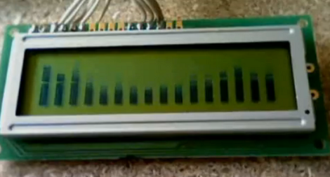
[El Artis] just finished building an audio spectrum analyzer that uses a character LCD. The uses an Arduino to drive the display, but unlike other meters that use the microcontroller for analysis, [El Artis] is using a discrete IC for that task.
This project uses the MSGEQ7 graphic equilizer display filter chip to grab frequency data from the audio source. The chip connects to your microcontroller of choice using two digital pins and one analog pin. [El Artis] points us to [J Skoba’s] post about how to use it with an Arduino, then adds his own custom character routines for an HD44780 display. You’ll notice that there are sixteen bars in the image above, which conflicts with the 7 outputs the chip offers. [El Artis] averages neighboring values in order to add the extra outputs.
Don’t miss the demo video after the break. If you’re looking to use this part in one of your projects, we noticed they’re a little hard to find (octopart doesn’t return any suppliers) but SparkFun has them.
[youtube=http://www.youtube.com/watch?v=EpLLqgySCD4&w=470]


I bet you could get the Arduino to do this by itself, without the extra IC.
It also happens that Sparkfun also sells a shield which does the same thing. It also uses that same chip.
My mistake. The shield is a bare one. It just contains the chips and connectors.
elm-chan got 128 fft bins pure in software, sampling at 9.6kHz. So 75Hz resolution.
Written in assembly, using fixed point math, running on a ATMega16 @ 16MHz.
http://elm-chan.org/works/akilcd/report_e.html
Really impresive proyect. Thanks for sharing.
Cool hack!
“. The uses an Arduino to drive…” :-)
“we noticed they’re a little hard to find (octopart doesn’t return any suppliers) but SparkFun has them.”
And eBay has them at half price, as usual. $4.95 per piece at SparkFun, $4.98 for two pieces (shipping including) on eBay:
http://www.ebay.com/itm/2pcs-MSGEQ7-7-Band-Graphic-Equalizer-ORIGINAL-MSI-chip-/140597842906?pt=LH_DefaultDomain_0&hash=item20bc48d3da
A long time ago i built a spectrum analyser with an ATMega8 and a graphical LCD from a Siemens phone. It got me to learn FFT although the code was written by someone else.
After that i wanted to build one with “discrete” components: opamps for filters, analog MUX, LM3914/5 and some supporting logic, all for a 16 band, 20 LEDs each analyser. I didn’t get to built it because of the lack of time and money.
The IC used in this project seems to be some early design for stereos. Hard to find and useless.
If you could make the same thing in code just in a mega8 or similar, why bother with the rare IC?
@bogdan: totally agree. Plus, interpolating for the missing frequency bands might give you a nicely looking display, but it’s highly unlikely to give an actual representation of the input signal.
Hello,
When I created the code I focused in the way for using the LCD as a graphical display when realy isn’t. May be the chip is not easy to find but the code of display representation is useable with a software using ftt.
Thanks for comments.