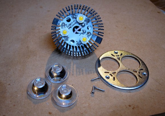
 Halogen bulbs put out a lot of focused light but they do it at the expense of burning up a lot of Watts and generating a lot of heat. The cost for an LED replacement like the one seen disassembled above has come down quite a bit. This drove [Jonathan Foote] to purchase several units and he just couldn’t resist tearing them apart to try out a couple of hacks.
The one we find most interesting is a PWM based dimming hack he pulled off with an Arduino board and a FET. The bulbs are designed to be dimmable through the 12V supply that feeds the light fixture. But the relationship of dimmer position to light level is not linear and [Jonathan] figured he could do better. His solution is to add a FET in parallel with the LEDs. When activated it basically shunts the current around the diodes, resulting in a dimming. The video below shows this in action. We wonder if the flashing is a camera artifact or if you pick that up with your eye as well?
You may also be interested to read his post on Gelling the LED bulbs. Gels are colored filters for lights (or camera lenses). He cuts his preferred color down to size and inserts it between the LEDs and the lenses.
http://www.flickr.com/photos/headrotor/9091073880/


I think he should have seriesed in FETs with each diode and PWMd those with a log function, as you could just parallel the gates. Shunting the current is not going to be very efficient as the darker the bulbs are, the more power wasted as heat!
Actually, he’s using a current source as supply. A series transistor would be a Bad Idea.
Shunting the load actually decreases power consumption.
Since it is a constant current source, would the fet just drop it to 0 volts?
Not to be nitpicking but IRF840 is a MOSFET, not a FET.
FET and MOSFET have not the same architecture.
So basically he’s shorting the power leads with a MOSFET. It must be the stupidest dimming circuit I’ve ever seen.
There’s a second PCB on the back side of the heatsink that the LED PCB is attached to. The second PCB is a rectifier and current source (usually 700mA). When a current source is shunted, voltage will drop to maintain current; shunting across the outputs of the current source results in a voltage drop; P=VI, and the limit of P as V approaches zero is zero, so this IS an acceptable dimming circuit.
In theory, but what happens in practice inside the regulator makes or literally breaks it.
If it’s a linera regulator, it will burn. If it’s a switching regulator, it will either shut down for short circuit protection, work well, work poorly, or work well but with reduced lifespan.
One of the problems with shunting the output to ground is that the output filter capacitor in the regulator is charged up to some voltage level determined by the load, and shorting it out causes a large outrush current that drains the capacitor, and a large inrush current as it fills up again. The dimmin circuit does this repeatedly at tens of kHz which causes a large ripple current across the output capacitor, which wears out the component faster, and forces the regulator to push a larger current into the capacitor to keep up.
If the component is designed to handle that, then it’s fine. If not, then the increased ripple current and higher losses lead to overheating and reduced lifespan.
No. It’s a common way to do high-performance LED dimming. National Semiconductor even has an app note detailing this kind of circuit for use with one of their constant current LED controllers. The power supply is actually a switch-mode current regulator. It only wants to supply a specific current (typically 350 or 700 mA). The output voltage may vary.
Some LED dimmers modulate the switch-mode regulator directly. However this can be fairly slow because of the time it takes the regulator to start-up and shut-down. To modulate the LED at higher frequencies (for example to get linear dimming without flicker) it is common to shunt across the LEDs since the transistor switches so quickly.
app note please
Look up the LM340x series of controllers. The technique will work with other switch mode controllers as well.
Certainly switch-mode power supply design is non-trivial but this is a reasonable way to do high-performance LED dimming. I should know, I’ve designed LED drivers using this technique.
I found it, snva342e.pdf, page 2. Yeah, looks like there is an app note (actually, it’s under the User Guides section on the TI site). It does show a FET bypassing the LED’s. However, it’s not going straight to ground. There is a resistor (R1A and R1B) in the circuit before it goes to ground. Between R1A/R1B and LED/Q4 is a connection going back to pin CS. According to the LM340x documents, this is the Current Sensing pin for the IC.
The resistors R1A/R1B does appear as R1 in the OP’s schematic but is listed as “optional”. I did not look over the entire document to see if this was really the case. But the schematic does not show it as such.
I don’t really understand where “Driver-” and “Driver+”in the OP schematic is going. Are they going back to a LM340x or equivalent?
I’m not an electrical engineer, I just know enough to get into trouble and to look for answers.
While that may be the case for specific regulator chips, it’s not a universal principle as the author of the website claims it to be.
It is not fine to short out constant current regulators, because generally that causes them to overheat and burn up. If you were to try this with a non-switching regulator, you’d end up releasing the magic smoke.
Exactly ! You dim the leds with a PWM signal sent directly on the feedback pin of the SMPS driver.
Shorting a regulator, whatever the technology, is bad. Period.
What makes it high performance?
The amount of time it takes to turn the LED on or off at the rated current.
1. LEDs apparent brightness is a non-linear function and the human eye is more sensitive to changes in intensity at low light levels than high light levels. So in order to make an LED dim in a visually linear fashion you must have a high dynamic range in the modulation of the LED. It is not uncommon to have a 4000:1 or higher dynamic ranges.
2. Some humans are very sensitive to the frequency of LED modulation (e.g. PWM period). Especially in certain conditions, for example when the LEDs are lighting sharp edges so that the modulation frequency can be seen as the eye sweeps past the edge. Although the common rule of thumb is that the eye can’t see PWM frequencies of greater than 100 Hz, in fact, lighting system designers often use 1 kHz as a bare minimum frequency and there are professional LED fixtures with modulation frequencies in the tens of kilohertz. A 1 kHz modulation frequency with a 4000:1 dynamic range means that the minimum brightness value results in a minimum on time for the LED of 250 nSec.
3. Switching power supplies switch the inductor at frequencies between something like 50 kHz and 2 MHz. Generally, the higher the switching frequency, the more expensive the supply. It takes a switching power supply a few cycles to establish a regulated output, meaning the maximum modulation frequency is limited (the inverse of the cycle count to establish a regulated output). The vast majority of commercial switching LED power supply solutions cannot achieve anywhere close to the 250 nSec requirement of the previous point.
4. Most LED drivers that support dimming by turning on and off (enabling) the switching regulator can only support a smaller dynamic range or modulation frequency. This is ok for some applications but not for others (e.g. color wash lighting). There are high performance parts, for example from Linear Technology, but the cost is also much higher.
5. Shunting, as in this example, is a low cost way to implement both high dynamic range and high modulation frequency for switching regulators that can support dynamic load voltage changes. The addition of the shunting MOSFET adds negligible cost and allows the use of inexpensive buck topology switch-mode regulators. Engineering allows the design of both a cost-effective and reliable dimming solution that meets all the regulatory criteria as well. There is nothing wrong with this design architecture from an engineering perspective.
Right not to confuse the newbs, but in the biz, we just call them FETs for short. Actual FETs and JFETs aren’t really used that often anymore. Maybe in audio stuff a little…
Have you ever looked at what the abbreviation stands for? They are all FETs, MOSFET is just a specific type of FET.
MOSFET = Metal Oxide Semiconductor Field Effect Transistor, or is that Fire Emitting Transistor? I always forget!
Cool but a transistor in // isn’t very energetically efficient…
what am I missing here ?
This is the equivalent of having the fuel in your car bypass the engine and dump straight into the exhaust. Sure you may get better ‘linear’ speed control, but at horrendous efficiency, surely
No. I can’t think of a car analogy here but basically as the source is a constant current supply if you shunt the current supply around the diode you won’t have any voltage drop. The powersupply for the LEDs will keep providing 30mA. 30mA * 0V = 0W of power.
Obviously this is idealised, but you can’t just open circuit constant current supplies or you get a massive voltage surge which if there’s any energy storage like a capacitor may kill your LED when you hook it up again if the voltage doesn’t come down fast enough.
However, you will never get 0 volts. And to make 30ma your regulator will put out some heat, too.
You get close. Rdson for a typical switching MOSFET is less than an ohm. Expect the FET to sink something in the order of 30-50mW. The powersupply is in a similar scenario. Switching regulators produce most of their heat during the switching while the MOSFET is in the active zone, not while it’s fully on or fully off. Your big risk in this case is the compliance of the powersupply. Can it get to 0V? If it discharges the output caps what will it do when it switches back on, will it overshoot? If you’re always depleting the cap the switchmode supply will experience similar effects to being extremely heavily loaded, i.e. high output ripple which can shorten the capacitor life if an appropriate one isn’t selected.
There are problems with this design, but power consumption isn’t one, unless the switching regulator isn’t able to get the voltage down due to design constraints. This may not a suitable design in every scenario, but in this case it works.
I’ve seen this happen a lot, so:
Maybe using a u-controller is a bit of overkill here?
A 555 and an op-amp would do the same.
I’m glad I’m not the only one who thought this…
“power LEDs are driven by a current source, which is completely fine to short.”
No it isn’t. While the current source will not be instantly damaged by shunting the current around the LEDs, it causes the voltage at the output of the regulator to drop to a few millivolts, which means almost all of the voltage now appears across the regulator, and the regulator heats up at a rate of U x I
In other words, the circuit is working at constant power by drawing a certain amount of current at a certain voltage. He’s simply shifting that power from the LEDs to waste heat in the regulator with this “dimmer”.
No. It’s a switching current regulator. The voltage varies while the current remains the same. Overall power will decrease while the MOSFET is on.
Yes, the output voltage varies, but the input voltage doesn’t. The difference between the input and the output voltage determines how much power is dissapated in a linear current regulator. That’s why it’s incorrect to say that it’s “fine” to short out a current source.
A switching mode regulator is a bit different indeed, but it’s still a horrible solution. Yet the author is saying that a constant current source is “happiest driving a short circuit” as if that’s their optimal condition, which is complete bollocks. He’s just confusing the concept of an ideal current source with current regulators.
And nowhere does it say it is actually a switching mode regulator.
+1
shorted, the voltage is 0V
Power = 0 * current = 0
In fact the voltage is not really 0:
V = Rdson * current
so
Power = Rdson * current²
but Rdson = 0.85ohm for the IRF840
You’re still looking at it from the point of view of the component that is actually doing the shorting, but that’s irrelevant.
The problem is that the regulator that is acting as your constant current source has all the voltage from your voltage source acting across it while it is supplying current to your short, so it dissapates power.
A switched mode power supply has a very good efficiency unlike a linear on.
I assume that the switched mode power supply has an efficiency of 1.
In this system the power is only disipated by the load.
But the real efficiency is not 1 it is probably around 0.8 or 0.9 and you are right saying that it is not a pretty hack.
It’s not necessarily wise to drop the output voltage of a switching regulator to zero either, because the output capacitor goes empty, and when you switch the shunt off it recharges back up to the voltage determined by the actual load, so you’re repeatedly dumping the capacitors.
Effectively, you’re driving a higher ripple current through the caps and that causes them to heat up due to their ESR.
Think about it.
Suppose you’re running a string of LEDs from a 30 volt source, at 300 mA. Let’s suppose they’re ten 2.8 Volt LEDs, and you use a current regulator to drive them. Obviously then, there’s 28 volts across the ten LEDs and 2 volts across the current regulator, and at 300 mA of current they’re dissapating 8.4W and 0.6W respectively, and the regulator only needs a small heatsink.
Now, guess what happens when you dim the LEDs by shorting the output of the current source? Yep, a short is zero volts across, so the regulator now has to drop 30 volts to put 300 mA across zero volts, so it has to dissapate 9 Watts or power.
And that has the obvious effect of overheating the regulator.
You’re thinking of a linear regulator. Lookup a buck-topology switch-mode regulator since that is probably what is being used by this light fixture. When the output voltage becomes smaller because of the switched on transistor, the regulator adjusts its duty cycle – essentially “sipping” from the input side less frequently.
Probably, but do you know for sure?
That’s the problem. You can short out -some- constant current regulators, but not all of them. The author on the other hand seems to think cc-regulators are ideal current sources and simply says that it’s fine on all accounts, which is horribly wrong.
Why not use the mosfet in series though and truly pwm the power going into the leds? Basically this is done for the heatbeds and hot-ends on all 3d printers. Just 1 mosfet with some pwm signal, not shorting it but just using it to drive the leds instead…
Um, if its a constant current source, that means its always trying to provide the same amount of current to the load, if the load is a short, the current source will try to drive that short, you don’t get a free lunch! If it’s driving that short, energy is wasted as heat! If that wasn’t the case the LEDs would never dim… You are shunting the current with a low impedence path away from the LEDs. Chopping the LEDs on/off with a series mosfet will only waste heat through the mosfet based on its on resistance, the rest of the current is powering the LEDs, which is light, not waste! When the mosfet is off, the source is recharging output caps or doing nothing, meaning no current drawn from the source by the load, which is MORE efficient. With this set up you are in effect powering either the LEDs or the short of the mosfet (lower R = higher I) FULL TIME. It may be better at a cheaters way of dimming the LEDs, but more efficient it is not. If the power supply is a switcher, caps across the output, series mosfet, logarithmic PWM to match the light output of the LEDs and there you go. Dax did a fantastic job of explaining this btw…
Both the solutions in this post are very wasteful.
Dimming using a parallel load is a crap hack. You really need to make use of the existing power supply to dim the LEDs, or if the constant current supply is fast enough, insert a series PWM controller.
Using colored filters on LEDs is also wasteful, especially since the LEDs usually don’t output an even spectrum of light. Get the proper warm white LEDs and don’t use color filters.
To all of you nay sayers out there, the site is called Hack a Day, not Good Hack a Day!
If this really is a way to reduce power consumption, why don’t we do it for everything. Make a constant current supply for everything, which according to the hypothesis here doesn’t use up power at all! And then shunt things to switch them off. You could short out your 3kW electric heater to save power. If you only short it out a bit, say with a resistor instead of a Magic-OSFET, then you could permanently run your heater at say 300W instead of 3kW and the resistor could be tiny because apparently it wouldn’t dissipate much power because the voltage across it goes down and we already decided that the current regulator wouldn’t dissipate any power.
But unless you have just invented perpetual motion, the point is that your ultimate power supply is (nearly) constant voltage not constant current so the power you don’t dissipate in the load because it is shunted still has to be dissipated somewhere along the line, if your load has 0v across it, the current source still has to drive the same current which means it has to get rid of all of the supply voltage (Vsupply – Vfet instead of Vsupply minus Vled).
I’m not disputing whether it will work as a dimmer, if the current regulator is capable of handling the load fluctuation then all will be fine. But it ain’t a perpetual motion/zero power machine.