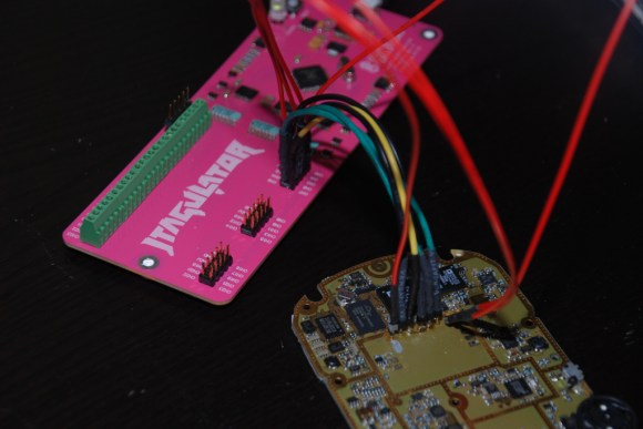
[Joe Grand] has come up with a tool which we think will be useful to anyone trying to hack a physical device: The JTAGulator. We touched on the JTAGulator briefly during our DEF CON coverage, but it really deserves a more in-depth feature. The JTAGulator is a way to discover On Chip Debug (OCD) interfaces on unfamiliar hardware.
Open any cell phone, router, or just about any moderately complex device today, and you’ll find test points. Quite often at least a few of these test points are the common JTAG / IEEE 1149.1 interface.
JTAG interfaces have 5 basic pins: TDI (Test Data In), TDO (Test Data Out), TCK (Test Clock), and TMS (Test Mode Select), /TRST (Test Reset) (optional).
If you’re looking at a PCB with many test points, which ones are the JTAG pins? Also which test points are which signals? Sometimes the PCB manufacturer will give clues on the silk screen. Other times you’re on your own. [Joe] designed the JTAGulator to help find these pins.
The idea is simple: Connect the JTAGulator to the test points on the PCB under test, issue a few commands via a serial terminal, and let the JTAGulator do the rest. It performs a brute force approach on every permutation of pins, issuing basic JTAG commands – either IDCODE or BYPASS, and looking for a response. If any valid responses are received, the JTAGulator displays the found interface’s pinout.
[Joe] used a Parallax Propeller as the core of his design. He added input protection, selectable voltage (1.2V to 3.3V) and bus pirate compatible headers. The JTAGulator can also identify and test serial UART pinouts to determine if any serial ports exist. If JTAG and serial aren’t enough, the JTAGulator is completely open source, released under the CC BY 3.0 US license. You can add any interface you want. Though [Joe] has plans to add more of the common interfaces in the future.


Where did they make those adorable pink pcb’s. Anyone know an etching service that does that?
+1
i also wanna know, might get my daughter into electronics
Follow up. Contacted them, it is http://prototron.com/
I love pink!
FYI boardhouses do not etch :)
It is regular PCB with pink solder mask and white silk screen.
You can google for “pcb service pink solder mask”
Follow up. Contacted them, it is http://prototron.com/
I just used my day job as an excuse to submit quotes for a full panel. Will keep you all posted (in the event you care) but I won’t be able to share specific numbers, sadly.
what a wonderfull device!
I wish I could easily get something like this. Currently of limited funds but would be willing to pay $20-$30. I have no means of building one myself (right now, no time, money, tools. etc). I have two jtag ports I need to access, one for a broken (?) printer control board and one for an old IR network interface. The later I want to re-purpose as a network-able IR beamer but need to reverse engineer it first.
Damn it Joe, get back on TV! You were great on Prototype This!
Holly crap that is expensive! 160$!!!
As he shows in the video, parts alone are $60, parallax are selling the unpopulated board for $20. A fully made up board, for 100% extra . . . .
Expensive? No. Not at all. Given a BOM cost of $60 + $20 PCB (well, $20 – markup) I’m impressed it’s that cheap.
If they’re using a US based fabrication house (and it would follow, a US based assembly house) then $160 assembled or $20 for a PCB are surprisingly cheap.
Even if one were to scale up (while maintaining good QC and using non-gray market parts) and move the fab. and assy. to China, India or Vietnam it would be difficult to meet the $160 price point and make a profit.
One thing I have learned well over the past couple of years is that electronics manufacturing in North America can be cost competitive with Asia when holding the Asian factories to the same standards as one would expect from domestic production. However, if you’re willing to cut corners and can accept a fairly high number of failures of deployed units, then Asian manufacturing is hard to beat.
All of this, of course, depends upon the process involved; PCBs that require machine assembly, impedance control, micro-BGA, etc. will, for the most part, be more cost effective to fab. and assemble in North America and sometimes even domestically. An Asian vendor may give you a better quote but by the time you factor in trips across the Pacific to check up on their process, production delays, QC problems, wastage, re-use of parts from said wastage leading to more QC issues, vendors trying to use knock-off parts, etc. it nearly always pays off to keep the manufacturing where you can keep an eye on it; Mexico City or even SoCal, South Bay, etc.
The two exceptions (in my experience) would be 1) if you have clout and really good relationships with vendors in Asia and 2) if you’re boards can be stuffed by hand.
All of this is from my own experience so feel free to disagree. In fact, if you know of some great vendors and want to pass along an introduction, please do!
Except that here there is not impedance control, there is not micro-BGA, there is nothing that _requires_ machine assembly… $20/board for a couple hundred two-layer boards is pretty up-there, they’re not that huge nor complex. And it’s not that complicated of a board, really, that it deserves a $80 retail markup.
Hell… I could probably redo the board so it doesn’t waste so much costly board area for the logo and stuff, and do the population by hand, and sell these for $100, which includes some profit for assembly. The author himself says the BOM cost is only $50 (plus PCB). Who wants one? :D
Yeah, I think the price is outrageous. Get an open source Bus Blaster built and ready to go for $34.95 instead.
Great job!
Any chance this is going into production somehow? Finding JTAG pins always is a pain in the proverbial arse, there are some solutions that can do it but I haven’t seen one that’s as nice as this one.
You can buy them from Parallax.
http://www.parallax.com/product/32115
The link shows it available from parallax: http://parallax.com/product/32115
At $160, its a bit of an investment.
Parallax about page basically says the company was started as a software pirating company
Now they upped the price to $189
I a few months we can get them from China for $3.41 a piece (if you take 1000 or more ;-)
This board can be cost reduced down to below $20 if one is willing to
cut a few corners. The majority of the parts are dealing with level
translating, protections and USB.
Most of that could be absorbed into a single microcontroller if you find
one that have 5V tolerant and runs on separate VIO supplies. This would
cuts down on PCB aize/complexity and BOM.
This board identifies JTAG pins, but doesn’t go beyond that. i.e.
programming, debugging etc. So you would want to add some OpenOCD driver
support for it to be worth while.
Hi,
Is there PCB for printig to do it myself or I didnt see it on oficial web or here :D
Thanks
JTAGulator ($200) vs. JTAGenum ($3)… Hardware Hacking Tools for Identifying JTAG Pins in Internet of Things Devices: https://www.praetorian.com/blog/jtagulator-vs-jtagenum-tools-for-identifying-jtag-pins-in-iot-devices