Here’s an impressive example of a completely home built magnetic levitation setup… with wireless power transmission to boot!
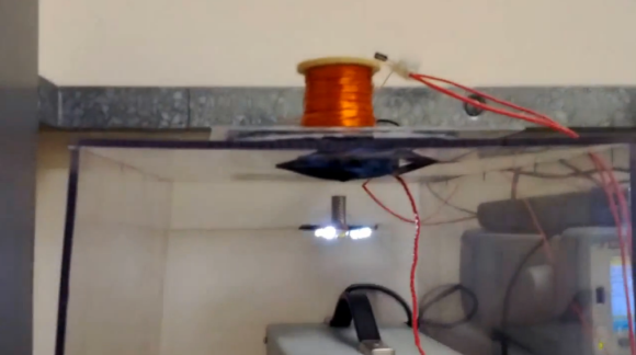
[Samer] built this from scratch and it features two main sub-systems, a electromagnet with feedback electronics and a wireless power transfer setup.
The ring of LEDs has a stack of neodymium magnets which are levitated in place by a varying magnetic field. This levitation is achieved by using a Hall effect sensor and a PID controller using a KA7500 SMPS controller.
The wireless power transmission uses a Class E DC/AC inverter that operates at 800KHz. Two coils of wire pass the current between the stand and the LEDs.
It’s very similar to a build we featured last year, but it’s a great hack, so we had to share it! Check out the video after the break.
Interested in more magnetic levitation? How about designing your own system using an Arduino? Or you can’t forget Hack a Day’s very own Portal Gun!


Wouldn’t it be fun if this was powered by that Brazilian big-ass gravity generator!
Now build a dance club with hundreds of those lighting it up!
You could even communicate with an RGB LED à la RFID!
I would operate at higher than 800KHz if using a Class-E inverter (although I am not sure if your using one coil for both power transmission and for levitation whereupon electrical length constraints may have set the coil operating frequency). See: https://spiral.imperial.ac.uk/bitstream/10044/1/10025/12/IPTTPE%20Pinuela.pdf for an example of 6 MHz transmission with high efficiency where the output inductance of the inverter is synthesized by operating the primary tank below resonance.
Now you can take a picture of this LED “UFO” model and sell it to the tabloids.
It fits with the anti-science anti-common sense theme.
That is super cool. I just got my own wireless power setup working last night.
The setup uses two coils; one for the levitation and one for the wireless power transfer.
The frequency of the Class E inverter can certainly be increased way above 800KHz which will allow power to be transferred at larger distances. However, higher frequencies will results in increased losses in the Class E inverter (since it will be difficult to tune it to operate at its optimum conditions) and the ESR losses in the coil due to the skin effect. Also, the Class E inverter will be very sensitive to the circuit board layout.
your aiming to optimise k^2Q_txQ_rx in a resonant IPT system (For optimal magnetic link efficiency). So maximize the Q factor product of your system. Optimal Q is found at the inflection point where Q starts to fall due to increased radiation resistance of your coil as Q is proportional to frequency but skin effect losses proportional to sqr(frequency) (unless your using litz wire coils).
Hook this guy up with these dudes:
http://hackaday.com/2013/11/30/gravity-powered-generator-real-or-fake/
This sounds like a fun project that I should try sometime minus the fact I’m far from being an engineer and being that knowledgeable with electronics :)
I wonder if you could ditch the complex levitation and use just a simple mains powered coil with a week horizontal permanent magnet.
Then make a board with an accelerometer in the middle, a micro controller, and three equal-lateral coils and 3 multicolour leds.
The coils would pick up the power and at the same time varying the load on them could be used for the levitation.
Also slight DC offsets to the magnetism of the coils could be used to rotate the board using the permanent magnet as a reference.
Then for example you could rotate the board in one direction while keeping a colour pattern still or even rotate the colour pattern in the opposite direction.
Any thoughts ?