We usually stay within the recommended Amperage with LEDs, but multiplexed displays provide an interesting opportunity to push them outside of that range. Because multiplexing scans a set of LEDs, they are not on all of the time. If your multiplexing setup allows you to remain within a certain time frame and duty cycle they can be driven past the constant current specifications. [Bryanduxbury] decided to take a look at the best way to overdrive LEDs.
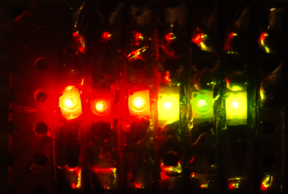
The example that he gives is that his 30 mA constant current rated parts can accept up to 185 mA but only for 0.1ms with a duty cycle of 10%. If you know how to apply these figures you can get them to shine much brighter. This becomes especially useful when your multiplexed display already has the light off for the majority of the time because the resulting average luminosity will be much higher. His side-by-side test is shown above. With a current limited LED on the left of each color group, a multiplexed LED driven at normal voltage in the middle, and multiplexing with overdrive on the right.
The biggest drawback that [Bryan] mentions is that if your firmware hangs for more than the spec’ed time you’ll definitely fry these diodes.


I still feel like this would shorten the life of your LED’s considerably, but for a one off it’s potentially a handy trick for someone.
It won’t. Really good LED venders like OSRAM, EVERLIGHT, CREE, etc etc include the “Permissible Pulse Handling Plot” in their datasheet. If not you can call their engineers and ask them for it. It’s a logarithmic plot of forward current versus time with multiple plots. I design high speed imaging systems so most of the time we take a 30mA LED and pulse it at 1 Amp or so. The shorter exposures result in better motion tolerance.
The sensor guys out there for IR based range also love to do the same thing.
I used to work for a company that made fibre analysis equipment, and we used exactly this trick. We’d pump a good 500mW or more through a 50mW LED, but we were strobing it 50 times a second for 15us or so the continuous power was in spec. The ultra-short flash time let us capture sharp pictures even though the microscope lens was moving rapidly. Some of these LEDs were in service for years with no significant loss in brightness.
LEDs that are expected to be used in a pulsed application, such as IR diodes and laser diodes will often explain in their datasheets what you can get away with when it comes to pulsed current vs. DC CW current. I don’t think a regular run of the mill diode is that much different than those. I think the main enemy is heating, and as long as you don’t overheat the die and keep the average current the same as specified for CW operation, it shouldn’t hurt anything or shorten the life any.
I guess the whole point here is thermals? If the diode doesn’t get too hot it’s probably OK. We can touch a burning hot frying pan too, but only for a fraction of a second :)
Or more if you are into that sort of thing, lol
It is not just a thermal issue. The PN junction can fry if the current is too big. But I guess that as long as it is not for too much time it is OK.
Amperage, really, what’s wrong with current :S
Is this an incorrect use of the word Amperage?
I suppose this crowd would also like you to use “electromotive force” instead of “voltage.”
>”amperage”
This does not work with china cheapie bulk led’s. Smoked a lot of them doing this as they barely work to begin with. You must use real grade A stuff, the Grade D garbage you get for cheap on ebay will not tolerate it.
reading and following the spec sheets will avoid time wasted on experiments
funny how people can understand LED current but they can’t grok “RTFM”
The cheap china-leds don’t follow their specs. The manufacturing tolerances are just too sloppy.
i dont think it is so much current as voltage and current combined because you can connect an led directly to a 3 volt source like 2 standard battery cells you can get in the store aaa, aa c and d and not blow the led
if you connect to 3 cells 4.5 volt then you will instantly pop the led or it will just burn out.
now a laser diode like used in cd/dvd and laser printers are very sensitive.
i believe they work at exactly 3 volts any more they can be damaged as well as no longer light up and any less they go out too.
i know you can parallel a bunch of leds on 1 resistor because some cheap toys do that.
i pulled a light saber ( i think it was a star wars) toy from the garbage can from a local car wash and it was made up of a string of 22 leds soldered in parallel.
Current and voltage you say? It’s almost like they are related. Most datasheets will give an Vf / I graph of how the LED responds. The trick you are seeing used relies on the poor current capabilities of battery cells, nothing more. Lasers are very similar to diodes in this respect, though blu-ray lasers seem to have a steeper relationship than others.
When you hook LEDs in series the forward voltages add together, any difference between the remaining voltage and the voltage source then determines the current based on the voltage source’s internal resistance. I.e. You may be able to happily connect a LED with a 2.5Vf to 2x AAA batteries, but expect it to pop straight away if you connect it to a 3V lithium battery or a powersupply as the internal resistance is too low to appreciably limit the current.
The V=IR relationship holds when you add more cells. So your same 2.5Vf LED connected to 3x AAA batteries will now see (4.5-2.5) / R_bat instead of (3-2.5)/R_Bat or a little less than 3x the current. Expect it to go pop.
Just because a toy does something doesn’t make it a good idea. Some examples:
– You can parallel a bunch of LEDs on 1 resistor, however due to manufacturing tolerances they will each drain a different current as the I/V curves are not identical on each one. Some may be dim, others may get damaged (remember the curves are steep). This is hardly efficient in terms of life expectancy or light emitted per component count.
– You can also run a bunch of LEDs in parallel from a single battery. This case often takes advantage of the battery’s internal resistance described above, or worse the LEDs underdrive i.e. they take a bunch of 3Vf LEDs and run them from say 2x NiMH batteries which will only provide 2.8V fully charged. Below the Vf LEDs still produce light but they are quite safe on the shallow part of their curve. You can often tell these ones as the brightness of the LED varies very greatly with battery charge.
In any case the correct way of driving an LED is with a constant current source. Some very expensive torches do this and you can tell this by an LED that stays at constant brightness for most of the battery life and then VERY quickly dies in its final moments. By regulating the current the LEDs can achieve maximum brightness and with control that prevents them from being overdriven, hence they will typically last the rated 100000 hours, unlike most toys.
Have seen similar data for over driving laser diodes. I think pulse timing is a great use of the FPGA-like “hardware” on a PSoC – firmware hangs (wifi, serial, debouncing…) don’t affect the pulses.
Please can we use the correct terms instead of just making words up ‘Amperage’ is not a word!
As Harowitz and Hill put it in The Art of Electronics, “Don’t call current ‘amperage’; that’s strictly bush-leauge.
Merriam-Webster appears to disagree with you, also I have heard a good number of people refer to current rating as such, perhaps it is a locational distinction.
http://www.merriam-webster.com/dictionary/amperage
Merriam-Webster is not a technical dictionary. There is the layman terms for things and there is proper technical term. We don’t need to dumb down for HaD, do we?
Are you suffering from Ampere rage?
http://www.oxforddictionaries.com/definition/english/amperage?q=amperage
http://dictionary.cambridge.org/dictionary/british/amperage?q=amperage
I can’t find a dictionary without the word in it (not to say there isn’t one), as mentioned before I have heard multiple people using the term in the sense that is used in the article which matches the dictionary description.
I am currently working on my masters in electrical engineering and depending on the writing I am doing I would feel confident in including the word amperage in my documents.
I would use word amperage to mean “current rating” when I talk to trade electricians and layman. Use whatever words depending on the technical levels of the audience. I don’t use terms like “doohickey” or “rig”, but might have to use it with other folks.
Nope. I don’t care either way, but quoting a common dictionary word usage for a technical term is kind of silly.
Everybody will know what you mean by “amperage,” but a significant portion of readers will think it makes the writer sound like a moron. “Current” avoids this issue.
Do you want to be “a hacker” or “a hack”?
Regardless, its capitalization in the post is wrong wrong wrong.
This is not overdriving the LEDs, the spec sheet usually contains the information needed when you are driving them this way in the same way as it specifies driving them with maximum current. If you do over drive them then they will fail. Showing brightness by taking a picture is not too meaningful as the shutter time plays an enormous part in the apparent brightness. It’s a complicated affair when considering the human eye but in terms of light output and power only, you will not get more light out of the LED than you will with constant current. In my opinion, look at the theory of operation. :)
As long as your shutter time is significantly longer than the PWM period of your LED, I don’t see what’s wrong with taking pictures to compare brightness. As long as the LEDs are in the same picture, as they are, they will be exposed the same. Or am I missing something?
film and eyes do not use the same mechanism for sensing light, the integration mechanisms are different, perception is complicated.
film can see the infrared output from LEDs and eyes cannot
film has a different response curve to light wavelength than eyes
it’s a pretty bold assumption to think that the film image has any relevance AT ALL to the direct viewing experience
True, but a modern SLR camera is highly optimised to mimick the human perception, right?
for the casual photographer maybe
but you are using equipment for purposes for which it was not designed
also the camera cannot correct for the imperfect film loaded into it
@F…. you know, we’ve had digital cameras for the two decades or so, right? That’s what he is referring to.
You can definitely use digital cameras to compare brightness if you do a few things:
a) Characterise the luminance response of your camera. (Quite easy, CCDs provide incredibly linear raw data)
b) The wavelength of the recorded object doesn’t change with brightness. If the wavelength shifts you also have to characterise the camera’s response to colour (beyer matrix, and QE vs frequency).
These are relatively easy to do if you know what you’re doing. You’ll find a lot of universities and R&D departments using commercial cameras for research purposes now, typically CCTV cameras as they come with greyscale sensors and don’t block IR.
Film? Who uses it anymore for still photos aside from a shrinking number of portrait photographers and hobbyists?
Same thing with tape. The media still often uses the anachronistic phrase “Caught on tape” for videos people have recorded on cell phones and all solid state (to harken back to the time when that was the new thing) video cameras.
Even worse is some news broadcasts and newspapers still use “Caught on film”. Use video or recorded and these days you’ll be right the vast majority of the time. If the still or motion pictures actually were taken with a film camera, say film.
For still pictures, photo covers all, no matter what imaging technology was used. Video works for any sort of electronic moving image recording method.
Save the use of the word film for when a moving picture was recorded onto actual film.
Another thing that will show the age of people using it is calling anything digital data is stored on a “tape”. “Plug that tape into the Atari wouldya?” “I put the tape into the DVD player but I don’t see the movie on the TV.” Particularly cringeworthy on this point is the movie “Cloak and Dagger” starring Dabney Coleman where everyone keeps calling the game cartridge a “tape”.
LEDs can be driven exceeding the power ratings and all will seem OK to start with but you will significantly shorten the life of the LED. Like bending a metal bar, you can bend it and bend it back again and all looks fine but you have created micro fractures in the metal causing a weak spot. Eventually when you bend it enough times it will snap.
another person who doesn’t bother to read spec sheets
“The candle that burns twice as bright, burns half as long, and you burned very, very brightly Roy.” – Tyrell
As long as you followed within the specs in a datasheet, then it is allowed.
I clicked this article just to read you nerds complain about amperage. Get a life, fools.
That says something about the “life” you have…
(Yeah, I know, don’t feed the trolls…)
But really he is right. Half the thread is having a decent discussion, the other half is bitching and complaining about the use of a word in the english language that seemingly everyone was able to understand.
On the subject of drfiving LEDs, when dimming LEDs with PWM, can the frequency of the PWM affect the lifespan of the LEDs?
I have read that this may be possible if the PWM frequency is the same as the resonant frequency of a bond wire. The micro heating and cooling effect causes the bond wire to flex and eventually damages the bond. You can see the effect of a damaged bond in an LED that flickers on and off when it is powered as the bond makes and breaks connection as it heats up.
If the LED is encapsulated, there is not going to be a lot of flexing for the bond wire. I have only seen the bare LED die and bond wires on PCB for old digital clocks.
A lot of PLCC packaged high-brightness LEDs (e.g. 5050 and 3528) and HB LEDs (Cree, Seoul, etc) have a gel-like encapsulation. Often pressing on the surface of these LEDs is enough to break a bond wire. My experience is that bond failures are a large portion of LED failures. I cannot personally speak to how often pulsing an LED might cause a bond failure but I can theorize how it might happen in some LED devices.
you don’t need to theorize
you can read the spec sheet
believe it or not, LED designers are familiar with this technique
A gel would dampen vibrations (i.e. lowering Q); helps to conduct heat away from the bond wire and increase thermal mass.
RTFM
Congratulations, you win HaD’s Laziest Reply Of The Day Award!
It is just a diode, an inductor and (optional) cap away from smoothing the chopped current to a LED.
which is fine, until you need it for something with >1 pixels
In my situation I’m using those LED strips with 5050 sized white LEDs, I run them at half-brightness in hope of extending the life, I’ve already had one strip ‘go bad’ after running at ful brightness for a Very Long Time[tm], a bunch of the LEDs overcooked and died which is my own fault really as I didn’t bother with proper heatsinking.
With the 2nd set of LED strips, stuck to aluminium for proper heatsinkinkg, using my own brightness control circuitry with remote control I found I had to run the PWM through a MOSFET at 40khz, if I set the frequency too low then the flicker became noticable, and anywhere inbetween I could hear a high pitch whine.
Hence asking if frequency is likely to damage LEDs. I’ve noticed some of the 600 LEDs among the 10 meters of strips aren’t as bright as 1 of the 3 diodes has stopped working, though it’s probably because the strips were cheap :)
What I find most interesting about this is the color-shift. I found this effect in some random surplus LEDs I was playing with some time ago. The closest I could find for an explanation is that the higher voltage (assuming constant resistance across the device) activates higher band-gap PN junctions incidentally manufactured into the semiconductor.
This made me wonder if LEDs could be intentionally made with a wide range of band-gap PN junctions to allow the manufacture of LEDs that have a full visual range of color, depending on the voltage at which they are driven. I didn’t pursue the concept further, as I didn’t think I would be able to get set up for custom LED construction for testing purposes.
And it seems that I’m not the only ‘Darren’ around right now. That is unfortunate.
“Hello, I’m Larry, and this is my brother Darrel, and this is my other brother, Daryl…”
I’ve experienced this with cheap green and blue LEDs. The Green ones would noticeably shine yellow when under driven – I even complained to the supplier because I thought they sent yellow ones (used a 3V coin cell to test). The Blue ones were a nice light aqua when under driven, but turned deep blue with a proper voltage.
Even if they can be made, they won’t make them that way commercially. I think colour purity, efficiency, lifetime, cost and yields (not sure the ordering) would be what they are looking for in a LED.
Use the PWM output mode of a timer pin to drive the LED. This is a hardware function, and it won’t matter if your firmware hangs. The timer will keep running and doing the PWM, which will keep your LED from turning funny colors and then winking out.
Another solution is to enable a watchdog reset timer which will reset your microcontroller if your code fails to “feed the dog” at specified intervals.
Shameless plug for my employer: The MAXQ622 has both of these features. See it here at: http://www.maximintegrated.com/datasheet/index.mvp/id/6526
Isn’t that assuming all controllers have a hardware PWM, or have such a free pin tied to a timer, or have a watchdog?
You know the reality as much as I do. Not everyone is going to use a microcontroller that has such an ideal configuration.
I have played with some of the old microcontrollers e.g. Z8, 8051,
68HC11, MC68HC908, PIC and they all have free running timer(s).
It is not so difficult to use the timer as a watchdog. Set the interrupt
vector to point to reset and once in a while your software have to load
the timer or it runs out and reset the system.
Some power supervisors come with watchdog function and all it takes is
an I/O pin you can toggle. You can of course wire up a CPU (not a
microcontroller) e.g. Z80, 6502 etc and memory without one if it pleases
you.
Did I mention we also make watchdog supervisor chips? ;-)
Ok, yes, granted, it’s not always possible to do PWM in H/W, but there are many ways to cover your butt just in case something goes haywire.
Of course, _I’d_ never to worry, since all my code is perfect on the first pass. o:-)
I have even implemented a PWM controller for LED brightness in 4
macrocells inside a PAL. It has a 3-bit counter and a 3-bit comparator
for the PWM. The rest of the logic was column decoder/driver for a
multiplexed display.
If you need something, implement it!
I have found that electronic components contain a little person named “Murphy”. Usually he just minds his own business but if you have exceeded the spec sheet in any way then he will release the magic smoke in a deliberate manner, usually right in the middle of the demonstration to your financial backers.
Me and a friend built a multiplexed display, after frying one LED due to the MCU freezing we added a timer on the row cycle, the timer enables the row drivers and if it doesn’t get another pulse after the display refresh time it turns off the drivers. The row driver was based on a 4017 and the display was 8 rows, so we put this timer on output 9. While this means we have a duty of 1/9 instead of 1/8 it means a very simple way of assuring your LEDs don’t fry. It would of course be possible to make 2 timers and AND them together, putting them on two different row drivers but that seemed like overkill for a patch on a simple display.
For all you worrying about blowing up LEDs when the code freezes (or when you reset the micro to program it), just use a lower current during prototyping! Make a few failsafe test programs to figure out the upper brightness levels, and use lower current during main code development until its all stable.
umm…. we should be worrying about the RMS power dissipated in the LED/diode? no? delivering 10ma in one second or 1A in 10ms at a constant voltage should not create a problem if the power rating is met. correct?