Have you ever built a wireless project and weren’t sure how to make one of those awesome (and cheap!) PCB antennas? “What low-cost solutions does our Antenna Board #referencedesign contain?” said Texas Instruments (TI) recently via Twitter. This older reference design contains some comprehensive designs for sub-1 GHz and 2.4 GHz antennas.
While TI’s documentation can be difficult to navigate, there are many hidden gems, and this is one of them. While TI created these designs for use with their wireless products, they will work on any device which utilizes the same wireless base frequency. For example, you could use any of the 2.4 GHz antennas with any Bluetooth, WiFi (2.4 GHz), or Bluetooth Low Energy chips. Simply open up their Antenna Selection Quick Guide document and navigate to the specific design for whichever antenna you would like to build.
For a more detailed overview of what goes into designing and testing a PCB antenna, check out this hack which we featured back in 2010. With the internet of things coming into its own, wireless projects will become more and more prolific, making PCB antennas more important than ever.


Stumbled on this: http://shutterfreak.net/blogs/olivier-biot/2010-06-13/eagle-library-245ghz-planar-inverted-f-antenna-pifa
Might be handy for Eagle users.
Are these free to use? I rember reading somewhere that many antennae designs are patented, since its so difficult to design good ones.
If it is for your own project then patents don’t matter. If it is product then you will have issues.
Technically, no, but no one will ever know.
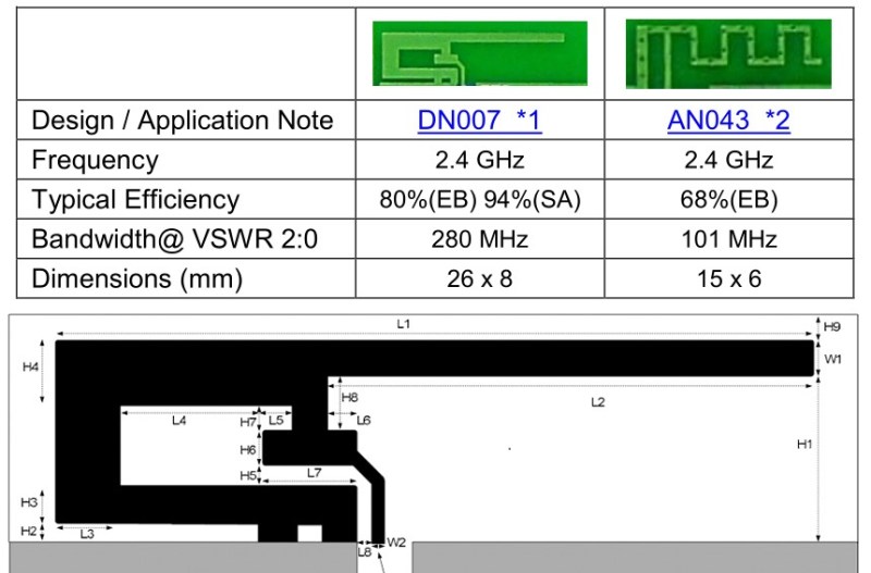
DN0007 is an impressive design.
Take care and consider also the bandwidth of the antenna and that the antenna matching varies if something (e.g. a hand) gets close to it.
Allthough the antenna on the right has 100 MHz, I would never use it for Wifi.
Thank you! Perfect timing..I am bumbling my way through creating a breakout board for the RFM69HW. This week I realized how clueless I was when it came to antennas on PCB. Now that I have a monopole wire figured out…unto integrating the wire into the PCB. A link to my follies: http://bitknitting.wordpress.com/2014/02/22/making-an-rfm69-breakout-board/
Great article! Thanks very much. I too am (was) trying to do a RFM69HW breakout board, but after reading your post I’ve decided I don’t really have the skills required. Probably good to find that out before I got too far along :-)
Instead I decided to buy a couple of RFM69HW breakout boards from here: http://modtronicsaustralia.com/shop/rfm69hw-breakout-board-with-module/
Test it on the weekend and they seem to work a treat.
Thanks very much. What are you building? Please keep in mind I am running from clueless every day. The only way I learned to do the PCB was through Chris’s Contextual Electronics class. He walks us through everything I did in the article. It costs some $, but is well worth it. I feel much more comfortable working with circuits – although I’m constantly making mistakes. The good news is I have not burned down our house (yet :-) ).
How do you get certified on those designs? I’m from Japan, and basically any Wi-Fi/Bluetooth/etc. device+antenna combo needs testing and approval here.
Yes how and if a board needs to be certified?, is something I have never understood?. If I made a small hobbiest board to sell, does it need to be certified, or is just the chipset and antenna design that is already certified? … If its used exactly as described in the docs, is it already certified? … (Modules are certified, but are chip only solutions also certified?). Does anyone know?
I may be wrong but this is what I understand. The chip/module and antenna combo must be tested together. For example, I have a laptop at home that is technically not certified because I upgraded the WiFi module (certified module from a different computer), but the antenna is part of the computer. Since that module was not tested with that antenna its certification is not valid in that configuration. Also modules come present certified because they are a finished product. Your PCB size and layout are part of the design, so you can’t just combine previously certified antenna/chip combos.
This next part I’m stretching for, but I think the certifications are granted to the manufacturer. So I don’t think you can you can use a module you made just because it was based on a design someone else got certified for. Also if your design would have to be an exact copy anyways.
As far as hobbiest boards go, that’s a grey area I don’t really understand.
If you want to sell it you will need to certify it as a unit. If you don’t mind possibly breaking a few laws you could use it as is and assume that your EIRP is lower then the regulatory limits. Coming from a guy that used to design antennas for a job, if you put these in a case probably will shift the resonance frequency and reduce the efficiency of the antenna enough that your EIRP will be below any limits in question.
but if you want to sell the thing you will need to get it certified. note these are reference designs and will need to change slightly for every aplication
I found an article over at Sparkfun that covers this topic pretty well.
https://www.sparkfun.com/tutorials/398
Check out http://openems.de if you want to design and simulate antennas. A simple example for a 2.4GHz PIFA is included (https://github.com/thliebig/openEMS/blob/master/matlab/examples/antennas/inverted_f.m)
These reference designs are a fine start, but know that the rest of the board is also participating as the counterpoise and this will affect your tuning. Also, any enclosure made with any material (even plastic) will change the tuning. With the resultant poor return loss, many chips will emit large levels of third harmonic energy, and reduce their transmit power.
To do this job right, you start with a candidate antenna and a working knowledge of RF layout at this frequency. You build a board, and measure the antenna impedance (real and imaginary) with a VNA, then figure out what to adjust so that the antenna is resonant, with enough bandwidth to serve the application, and then match the impedance back to the chip.
Then you build that and re-test.