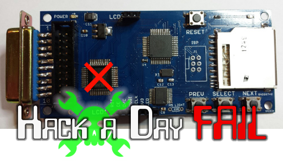
The card you see above is a floppy drive emulator for Macintosh. [Steve Chamberlain] has been hand assembling these and selling them in small runs, but is troubled by about a 4% burn-out rate for the CPLD which has the red ‘X’ on it. He settled into figure out what exactly is leading to this and it’s a real head-scratcher.
He does a very good job of trouble-shooting, starting with a list of all the possible things he thinks could be causing this: defective part, bad PCB, bad uC firmware, damage during assembly, solder short, tolerance issues, over-voltage on the DB connector, or bad VHDL design. He methodically eliminates these, first by swapping out the part and observing the exact same failure (pretty much eliminates assembly, solder short, etc.), then by measuring and scoping around the card.
The fascinating read doesn’t stop with the article. Make sure you work your way through the comments thread. [Steve] thinks he’s eliminated the idea of bad microcontroller code causing damage. He considers putting in-line resistors on the DB connector but we wonder if clamping diodes wouldn’t be a better choice (at least for testing purposes)? This begs the question, why is he observing a higher voltage on those I/O lines during power-up? As always, we want to hear your constructive comments below.
 Fail of the Week is a Hackaday column which runs every Wednesday. Help keep the fun rolling by writing about your past failures and sending us a link to the story — or sending in links to fail write ups you find in your Internet travels.


Perhaps the ground connection is made later than most of the IO pins, and neither side uses an isolated supply.
Any chance the failing parts are counterfeit?
One of the comments mentioned this. I would look at the possibility of latch-up occurring, especially since it looks like the CPLD is connected directly to the cable going to the Mac. It’s possible that he’s seeing voltages in excess of the CPLD’s capability to mitigate, triggering the latch-up. Hopefully the resistors will help with that.
The description of the problem sounds a lot like latch up.
“or bad VHDL design” actually, reading his page, I can’t see where he mentioned that (the most was point #3 about a software collision with the AVR but he dismisses it as ‘hard to go wrong’ – that doesn’t sound validated!).
Having felt a high-end gate array go themal (and sink way more current than expected) because of a design issue, I’d double check the validattion of the CPLD logic (10% sounds like a corner case that isn’t obviously spotted by pure eye-balling the code).
From his blog comment: “I’m still not convinced that 240 us of over-voltage or bus contention on the I/Os is long enough to cause a problem”
LOL!!!!! — Isn’t this longer than a lightning strike lasts? But surely; knowingly subjecting the part to an overvoltage that is specifically warned again by the manufacturer in the datasheet COULDN’T be a sign of a potential issue….. ~CERTAINLY~ :D
Bus contention between two output drivers is hardly ever a problem. With combined impedance of about 100 Ohms, current is limited, and with 240 usecs, time is too short to cause excessive heat. It would also not explain 400mA currents.
Short bursts of over (or under) voltage could be a problem, though, depending on the voltage and current.
300+mA sound like a case for latch-up. 4% sounds too high for bad components coming from a factory.
While the CPLD is powering up, its VIO/Vcore supply is low. So the only possible type of bus contention would be the CPLD driving its I/O line low while the I/O is high. The old MAC era parts are either TTL or NMOS which have very weak IOH, so it would be unlikely for that to have enough current to cause a latch up.
Series resistors (100 ohms like one of the comments in the blog) are good idea for SI reasons (Why they aren’t there in the first place?) and they do limit the I/O current so that you won’t get a latch up from there.
I would look at the Mac & CPLD power supply rail and the I/O rail closely to make sure that they are within specs when the Mac powers up. i.e. no funny spikes etc.
I do hope you know how to measure stuff properly with the scope probes *properly* for these type of work and keep the loop area small. http://www.sigcon.com/Pubs/edn/probing_for_noise.htm
Seem to be a general lack of protection on that PCB. I don’t see any bypass capacitors, unless they’re hiding on the bottom.
It’s always a good idea to add protection to any IO leaving the board. You can always depopulate it if you don’t need it.
That reminds me of something. Double check the linear regulator datasheet to make sure that you have met the minimum input/output capacitance requirements (and sometimes the ESR) and/or minimum load.
Older LDO tends to be a bit picky about about those and can go unstable if the wrong type (e.g. ceramic caps because of low ESR) is used or the values is out of spec (usually a case of it being too low). Unstable means overshoots or goes into oscillations etc under certain loading conditions which I don’t think the CPLD would appreciate.
Did he attempt a JTAG wiggle test to determine which pins were damaged? That would really help him narrow down what is causing the issue.
One of the things to try is to measure the current of the VCore and VIO separately to see where that extra current is going to.
If it is latch-up or I/O related issues, VIO rail would be the one with high current.
From the link “The CPLD is a surface mount chip with tiny 0.5 mm pin spacing, so there’s no way to connect an oscilloscope or other probe. ” A soldering iron and wire-wrap wire is your best friend in these cases. Just solder a wire tail onto any pin you want to probe. Alternatively, you can scrape the solder mask off a section of the trace you want to probe and solder a tail onto that.
The other thing I’d do is to lift some of the CPLD pins and solder in a testing circuit. Soldering a 1ohm 0402 resistor vertically under a lifted power pin with wire-wrap tails will let you measure chip current. Similarly, an 0402 resistor under the IO pins to the old Mac would allow testing of series resistors without making a new board.
Optoisolators?
Damn, stole my idea. That and some on board regulators. Never hurts to make sure you’re NOT above the rated max values for the chips.
oops, didn’t visit the page and do a thorough read….looks like he’s got a regulator, but if the rating on that is just above expected input voltages and output current, he’s in that grey area where your percentages may work against you. Perhaps fusing the power line over to the CPLD so if it begins pulling too much current it disconnects before excessive failures in the chip cause something to really burn.
But optoisolation of the data lines would be a great place to start. I’ve seen it happen where you create a potential via the data line that sinks the entire circuit.
I saw the long cable you are using on your blog, this cable means a higher trace inductance! Higher trace inductance also means more ringing on the wire, and on the i/o pins of the CPLD. The higher ringing leads to higher voltage/energy and therofore possible destruction of the i/o pins. To see this ringing you’ll need a very low capacitance probe for your oscilloscope (and just because you can’t see it, doesn’t mean it isn’t there)! The series resistors will fix this most likely as they protect againt higher current and also a bit against overvoltage. This works for the signal wires … for the supply voltage use tsv diode plus ceramic c 100n+10pf + tantal 100uf+. BR René