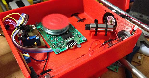
Precisely applied ultraviolet light is an amazing thing. You can expose PCBs, print 3D objects, and even make a laser light show. Over on the Projects site, [Mario] is building a machine that does all of these things. It’s called the OpenExposer, and even if it doesn’t win the Hackaday Prize, it’s a great example of how far you can go with some salvaged electronics and a 3D printer.
The basic plan of the OpenExposer is a 3D printer with a small slit cut into the bed, and a build platform that moves in the Z axis. The bed contains a small UV laser and a polygon mirror ripped from a dead tree laser printer. By moving the bed in the Y direction, [Mario] shoot his laser anywhere on an XY plane. Put a tank filled with UV curing resin on the bed, and he has an SLA printer. Put a mounting bracket on the bed, and double-sided PCBs are a cinch.
The frame is made of 3D printed parts and standard RepRap rods, with the only hard to source component being the polygonal mirror. These can be sourced from scrounged laser printers, but there’s probably some company in China that will sell them bulk. The age of cheap SLA printers is dawning, friends. Video below, github here.


Awesome build. Looking forwards to the day I see a working homebrew sintering printer.
BTW What about covering PCB in toner powder and use DVD-RW laser to selectively bake it to surface?
Because you’ll get toner powder EVERYWHERE, it’s nasty.
spray paint a pcb in acrylic based paint and laser etch the negative of your circuit pattern. problem solved
Whenever I’ve seen projects that use a laser to scan across to expose a PCB the problem has been that you either need a very powerful laser or it takes a very long time. I can imagine the same might be the case for SLA printing too.
40 watt co2 laser tubes from China are cheap enough to be considered disposable now.
I know that’s not necessarily the right kind, but it proves the technology exists.
I know – I’ve got one. However this project isn’t using a 40W laser. And CO2 laser are IR, not UV.
Well, you need more N2 in the mix, instead of CO2 and that’s it.
The beam is, for the lack of a better word, utter shit. You can’t get the needed coherence for it to pass through the scanning optics…
Perhaps you mean beam quality? Coherence has nothing to do with focusing optics unless you’re really worried about preserving the wavefront quality in applications where phase stability is very important (i.e. fringe contrast for interferometric applications, holograms, etc.. )
Diodes tend to have poor mode quality because the output beam isn’t symmetrical, and usually highly divergent. On top of that, the optics that come with these crappy little diodes are usually low quality (plastic) and not well matched to the NA of the beam divergence. In short, they’re not designed for any application which requires any of the ‘usual’ desirable qualities in a coherent light source..
Ben Heck did a video on how to make PCBs by painting them, etching the paint with the laser, and then using a conventional PCB etching process to finish it. At Texas A&M, they did something similar for “rapid prototyping” PCBs, though I have to say that their process for making vias is anything but stellar….
Can you elaborate on how they did vias? just curious
The price of a sla printer could be $0 and it still wound’t be a good deal, the uv cured resin costs $500 a gallon.
No it doesn’t. Makerjuice is about EUR150/gallon iirc, ex shipping.
Thanks. That is corret. And It will never be cheaper until we have more Open Source SLA printers!
From Makerjuice, the price (including shipping) I see is about $180 for 4 liters.
I found a gallon (3.88 liters) for 92 usd on ebay.
No, per unit of mass, UV resin is pretty competitive with “filament plastics”
Give it another year, and it’s going to be *cheaper* to print a thing out on a resin printer.
Most printed objects are hollow or contain very little volume. A gallon of water is approx 8lbs or 3.6kg. Given that most filament is sold at around $40 for 1kg, we’re talking $180/3.6kg or $50/lb of resin. – Not a heavy premium from filament-based printers.
I have one of those spinning polygonal mirrors, but I have no idea what voltage to drive it at. I can’t find it in these build details, anybody know?
Is it the kind driven by a flat brushless motor? If it’s on the board then the driver chip is likely near by. Read it’s number and find it’s data sheet and that will tell you. Of course this depends on a lot of ifs, I’m not sure if your mirror is even on a board.
Why does it have to be a rotating mirror? Why can’t they just use a galvo? Much simpler, and you can DIY the whole thing.
It would make the software more complex, because you’d have to compensate for the acceleration/deceleration curves at the ends of the galvo’s swing (cf. the patent for the RTI displays used in the Nintendo Virtual Boy).
Hi, last time I tinkered with one of these (Apple printer), they needed +8V.
A lot of these also have outputs for position and motor phase which can be used for real time feedback.
One big problem with the optics mentioned earlier can be overcome if the correct optics (ie glass) are used, plastics and UV just don’t get along.
A big improvement could be to use multiple beams on different mirror facets combining at the end into one large but somewhat focussed beam, using beam shaping via cutoff slits and removing all but the last optical components also helps.