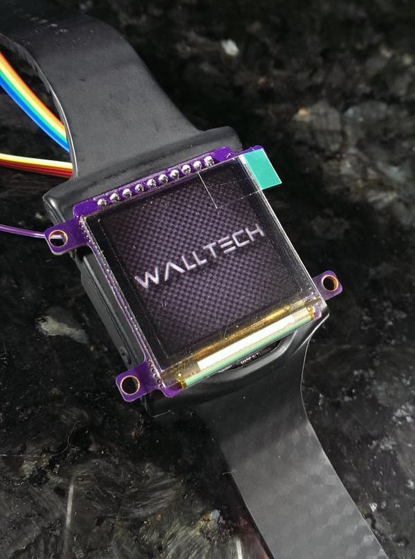
While there is lots of hype about a big company launching a new wearable product, we’re more interested in [Walltech]’s open source OLED Smartwatch. This entry into The Hackaday Prize merges a collection of sensors and an OLED screen into a wearable device that talks to your smartphone over Bluetooth Low Energy.
The device is based on the IMUduino BTLE development board. This tiny Arduino clone packs an inertial measurement unit (IMU), a Nordic nRF8001 Bluetooth radio, and an ATMEGA32u4 microcontroller.
The 1.5″ OLED display comes from [miker] who makes an OLED module based on the SSD1351. A STP200M 3D pedometer provides activity monitoring in a tiny package.
On the hardware side, packaging all these components into something that will fit on your wrist is quite difficult. The prototype hardware is built from mostly off the shelf components, but still manages to be watch sized.
At this point, it looks like the code is the main challenge remaining. There’s a lot of functionality that could be implemented, and [Walltech] even mentions that it’s designed to be very customizable. It even supports Android; the Apple Watch can’t do that.
 The project featured in this post is a quarterfinalist in The Hackaday Prize.


What an ugly PCB… Stop using right angle traces on PCB!
As a bit of a perfectionist, a like the spacing and angles of all the traces to be consistent and organized, and by holding shift while dragging traces, I can get perfect right angles that are the most space-effective way of routing connections on a rectangular PCB. I despise autorouters, and in fact, hate curved traces on vintage boards as much as you hate right angles, and 45 degree angles are almost impossible to get right, so that’s why I use right angles. (I also think they look cool)
According to my 30 second Google search, Right angle traces cause impedance changes and are thus prone to EMI issues. This is due to the line width changing sharply, so it is generally advised to break it into 45 degree bends, or ideally a round corner. That’s what she said.
Good to know. For this project, that’s not an issue, but I’ll certainly take it into account for sensitive or high power projects.
I was looking for design that i could make into cycling computer connected to my smartphone.it seems to be a nice place to start. and as it isnt on the wrist i can bulk it up a little bit without any worries.
A great start by such a young enthusiast, however a more thorough understanding of the electronics inside all those modules and Arduinos would lead to a watch that is far more capable, compact and cost-efficient. Also, perhaps some research could be done in finding and implementing a circular display (such as the one on the Motorola watch).
Good luck with that – try it yourself…
+1
Good luck with that IMU*BTLE thingy. Looking at the PCB, it looks as if the guy designing it took the nRF datasheet too literally and just wired the last pass inductor to the shunt capacitor with no antenna connected there. Ugh!?
Nice work for a prototyping platform. Obviously it can be cost and size reduced by removing modules but thats okay. Seriously though scrap the right angle traces. It screams amateur and is a bad habbit. See “acid trap”.
I think there is an antenna on the imuduino. It’s near the connector. It’s a molex part that looks like a little tower, I think an LDS antenna.
What’s the battery life like? And why such a wimpy mcu?
Indeed, the antenna is there. I have seen that funny Molex part before. I’m still not convinced regarding the potential RF performance of the layout, given the way the antenna is fed and how is the balun dispersed through all other circuitry.
(OK, I can be wrong, as has shown with the antenna already and just guessing from pictures, but the antenna feed, even if considered a microstrip, is certainly >100ohm (and I am still counting 0.2mm wire width, which is both unlikely).
But hey, I am not a RF pro anyway ;-)
Try designing an RF circuit without RF testing equipment, sans coffee, at 4am in the morning. :-)
I’m surprised it worked on the very first revision. The traces are all 5mil, w/ 10mil spacing. 4-layers.
The choice of ATMEGA32u4 was done to remain compatible out of the box with the Arduino set of tools (IDE, bootloader). Since we are such a small shop, we can’t support a custom bootloader, and customized SPI, I2C, etc. libraries yet.
We are working on a new board for folks that need something other that Arduino. How about an STM32f439zi BGA based board about the same size?
For now, we wanted to support [Walltech]’s project with everything we could …this is what we had at the time. His smartwatch, no matter how you approach it, is flat out *FANTASTIC* (it even predates all these new smart watches made by big names)
Oh sure I did. Well, till 1AM only, hand-placing 0402s gets really hard after that.
Specifically when doing this w/o proper equipment, I would stick much closer to the vendor recommendation (Nordic, as other chip makers, publishes nice reference layouts for the RF part). But hey, it’s a wearable, Walltech’s not aiming at 50m reach.
And yeah, with 4-layer, you’ll be much closer to a reasonable trace impedance at least – assuming you have a good groundplane directly underneath.
Thanks for showing up!