

Amateur, or ham radio operators have always been hackers. For much of the early 1900’s, buying a radio was expensive or impossible. Hams would build their own rigs, learning electronics and radio theory along the way. Time moves on, but hams keep hacking. Today we’re highlighting some of the best ham radio projects on Hackaday.io!
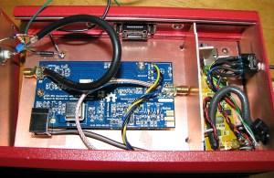
We start with [DainBramage1991] and his very practical RTL-SDR With Upconverter and Case. [DainBramage1991] fell in love with his low-cost RTL software defined radio dongle. He even added a Ham-It-Up upconverter to cover HF bands. The only problem was RF noise. the Realtek USB sticks tend to have little or no filtering, which means they are very susceptible to noise. [DainBramage1991] used the time-honored technique of insulating with copper clad board. Bits of PCB hold the RTL-SDR and upconverter in place. More PCB separates the two boards. Everything goes into a steel enclosure which keeps that unwanted RF at bay.
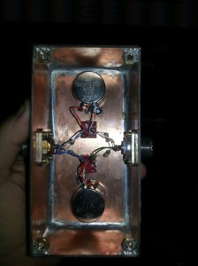 Next up is [Ryan Miller’s aka KG7HZQ]’s ham radio fox hunt attenuator. Ham radio fox hunt’s don’t involve baying dogs or horses. In this case a fox hunt is a contest to find hidden low power transmitters. If you’ve never tried one, it’s a heck of a lot of fun. One of the challenges with a fox hunt is to find the direction to the transmitter when you’re very close. Even with directional antennas, reflections and swamped receivers make it hard to figure out just where the transmitter is. The solution is an attenuator, which simply reduces the signal to a more reasonable value. [Ryan] also used copper clad PCB for his circuit. Since the attenuator parts are soldered directly to the PCB, this is more of a Manhattan style design. Two ceramic 1k pots help him achieve his goal of near perfect linear attenuation. We’re betting this attenuator will help [Ryan] win some contests!
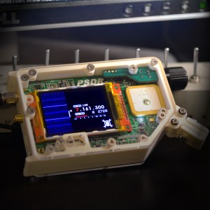 Who says amateur radio won’t take you places? It may well be taking [Michael R Colton] to space! [Michael’s] project PortableSDR is one of the five finalists in The Hackaday Prize. We covered Michael earlier in the contest. PortableSDR started as a ham radio project: a radio system which would be easy for hams to take with them on backpacking trips. It’s grown into so much more now, with software defined radio reception and transmission, vector network analysis, antenna analysis, GPS, and a host of other features. We seriously love how [Michael] optimized a small LCD for waterfall display, tuning, and bandpass filter adjustment.
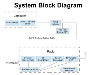 [W5VO] is working on an Ethernet to Radio Adapter. Every foot of coax in a radio system loses signal. Connections are even worse. It can all add up to several dB loss. [W5VO] wants to put an SDR at the antenna feed-point. With the signal path minimized, more watts make it out when transmitting, and more signal gets back to the receiver when listening. The interface between the SDR and host computer will be all digital; Ethernet to be precise. [W5VO] isn’t the first person to do something like this, microwave systems have had the transmitter and LNB at the antenna for years. That doesn’t take away from [W5VO’s] design at all He’s been quiet for a while, but we’re hoping he continues on his design!
Where is everyone else? We’re a bit light on projects this week, but we have a good reason. There just aren’t enough ham radio projects on Hackaday.io! We’re hoping to change that though. Are you an amateur radio enthusiast? Document your project on the site. Get input from other hams and push the envelope! You might even find yourself on the Ham Radio List!
That’s all for this episode of The Hacklet. As always, QRX is next week. Same hack time, same hack channel, bringing you the best of Hackaday.io! 73’s!


Magical electrical wizards
Not sure if it follows good RF practice… The still attached connectors on the PCB forms a stub.
In the HF range and even in the 125MHz IF Range I think those little connectors are way too small a fraction of a wavelength to be an issue. If the signal is being fed through the converter board, even when the converter is not on then it might be an issue when he gets up to the very highest frequencies the RTLSDR can handle. Even then… I’m not sure it would be that big of an issue.
>After adding a Ham-It-Up upconverter, I had the ability to observe signals from DC to 1.7 GHz.
125MHz is not the highest frequency…
Certainly this should not be in the same post that talks about RF losses when connectors and cabling becomes an issue.
No, but RTL-SDR’s have a functional floor of about 70-80MHz, so the upconverter enables the receiving of HF and low VHF(moving the low end of those bands to 125MHz, or whatever based on the LO of your choosing. 110 would be better), which would otherwise be unavailable.
Up to 1.7GHz on other coax with that other extra PCB mounted connector. Why are you focused on the 125MHz side?
One can get away with stuff, but that is still sloppy. Do it right, use a cable with proper connectors on both ends or desolder the existing one if you are cheap on connectors. It is that simple. Hell you get to recycle 2 connectors for other stuff.
To everyone concerned about good RF practice: You are probably correct. If this device was a transceiver, I would have been much, much more careful in constructing it. However, it is a receive only device, and the frequencies I’m interested are all below 500 MHz. I left the connectors in place in case I decided to rearrange things later on. The coax was selected because it’s what I had on hand. The same is true of the case, the wiring, and everything else in this project, with the exceptions of the SDR and upconverter. It is truly a junkbox special. I am a tinkerer, and I put this together the way I did because it improved its performance considerably. I’m certain there is room for more improvement, but for now it suits my needs quite well.
As for the frequency range, I have it set up with 2 modes, controlled by a DPDT center-off switch: With the upconverter active its range is 0 Hz to roughly 50 – 60 MHz. With the upconverter bypassed, its range is 24 MHz to roughly 1.7 GHz.
This are delightful projects, but some of us don’t have much free time to build. Someone might themselves up in business selling these gadgets assembled or almost assembled.
–Mike Perry, KE7NV
Thanks for featuring some ham radio hacks. It’s a hobby with a lot of DIY builders and experimenters, and I find these sorts of projects very interesting.
–Richard, AG6QR
Richard – I’m hoping we’ll get a few more of those builders to document their projects on Hackaday.io.
I can’t count how many cool ham projects I’ve seen in person at hamfests and other events. Some of them end up in magazines, but many of them go undocumented. Hopefully we can change that – Adam KD2BDF
Thanks for highlighting our projects and ham radio in general, Adam. It’s an incredible hobby with something for everyone.
I honestly never considered ham as a hobby until I got the RTL-SDR; it seemed too expensive/low tech for me to take an interest. Boy was I wrong- radio design and ham in general is crazy cool.
I suspect many people are the same, a lot of HaD readers are probably more interested in the latest digital hardware hack than radio hacks, as cool as they are. It’s easy to see how cool a blinky pov thing is, whereas something cool in radio needs a bit more knowledge. I suspect cheap SDR will actually make this sort of hack much more common.
Awesome project links. The foxhunt attenuator isn’t really a great executed idea. The best way to attenuate is to mix a frequency with your desired signal. Then instead of being overloaded at that frequency when very close you are actually listening 4Mhz off and you can get a small usable signal still.
I use one of these I built ten years ago. I thought everyone did it that way! He he.
VE1FX
Although I do like the idea of a simple passive circuit. Hmm maybe I changed my mind…
VE1FX
Ryan Miller KG7HZQ I built the fox hunt attenuator. being a new ham I found i enjoyed fox hunts but needed an attenuator to get closer then 50 feet. saw some cool stuff stole ideas from everywhere. its a 3 way design. straight pass through. 0-21 db attenuation and 22-60 db. completely linear. completely passive. didn’t want to get out to the field and have a dead battery or find i left the switch on. if anyone has ideas or suggestions on how to improve the design im open.
Looks very well put together to me. The only thing I might suggest is to add a second (or multiple) stage of attenuation that you can switch in or out as needed.
I like that it’s completely passive. That makes a lot of sense when on the move tracking down a fox. It also looks small enough to be comfortably zip-tied to your antenna.
Well since you asked… =)
http://www.eevblog.com/forum/testgear/sainsmart-dds120-usb-oscilloscope-%28buudai-bm102%29/
It’s an USB o-scope. It doesn’t have a tuner nor AGC. Its sodware (misspelled, but left it as-is) is barely serviceable. It’s price, however, is unique. Some brilliant people are about to RE its protocol and then you might hear a lot more about this device.
What I’m doing is looking into what it is that seems to cut host-side USB 2.0 transfer rate in half at best in every implementation I can find. It doesn’t appear to be a hardware limitation.
My plan is to throw most of what makes the USB protocol into what it is out the window since obviously it is slow and no good. DMA support is common in USB hardware, so there is no reason why one should not be able to get 96MB/s from a single device.
http://sdr.osmocom.org/trac/wiki/fosphor should be able to handle 96MB/s and more, so my task is actually very simple.
Blargh. 96MB/s is on the front side of the FX2. I got some work to do after all. >_>
I’m still working on my SDR cape for the beaglebone black!
https://hackaday.io/project/2185-BlackRock-SDR%3A-BeagleBone-SDR-cape
I made a hackaday account just because of this article. I really like the project pages. I will be posting most of my work here now.
I have created a raspberry pi powered fox hunt transmitter please check it out.
http://hackaday.io/project/3325-pifox