No one is sitting around their workbench trying to come up with the next great oscilloscope or multimeter, but function generators still remain one of the pieces of test equipment anyone – even someone with an Arduino starter pack – can build at home. Most of these function generators aren’t very good; you’re lucky if you can get a sine wave above the audio spectrum. [Bruce Land] had the idea to play around with DMA channels on a PIC32 and ended up with a function generator that uses zero CPU cycles. It’s perfect for a homebrew function generator build, or even a very cool audio synthesizer.
The main obstacles to generating a good sine wave at high frequencies are a high sample rate and an accurate DAC. For homebrew function generators, it’s usually the sample rate that’s terrible; it’s hard pushing bits out a port that fast. By using the DMA channel on a PIC32, [Bruce] can shove arbitrary waveforms out of the chip without using any CPU cycles. By writing a sine wave, or any other wave for that matter, to memory, the PIC32 will just spit them out and leave the CPU to do more important work.
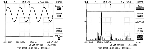
[Bruce] was able to generate a great-looking sine wave up to 200 kHz, and the highest amplitude of the harmonics was about 40db below the fundamental up to 100 kHz. That’s a spectacular sine wave, and the perfect basis for a DIY function generator build.


The zero CPU cycles assumes that the frequency of sine wave you want is an integer number of sample periods long, so will cause issues if you want an arbitrary frequency output.
You can prepare a sample that consists of multiple periods to increase the resolution.
Indeed, perhaps I should have been more specific. The condition of requiring a signal which is repetitive in an integer number of samples will still limit your frequency resolution, especially at output frequencies which approach your sample rate. Mind you, if you wanted to create a signal generator with a PIC32, I would have thought it would be able to generate a sine wave on the fly at 200kSPS, where DMA would still be useful to transfer update the DAC register and regular intervals.
200kSPS would be easy, but quickly looking at the source code, I think the sample rate on this design is 1.28MSPS, which would be a challenge.
BS. Change the cpu clock frequency.
The system PLL can only operate in a limited number of configurations, so that won’t help much.
An external PLL (e.g. Si5351A mentioned on HaD previously) *could* be used to change the frequency feeding into the PIC. That would make things more complicated and can screw up things e.g. UART/USB/RTC/OS that relies on a particular frequency.
And if you’re willing to go that route, it’s probably smarter to use an external DDS chip instead.
>Note that B.4 and B.5 have a required config statement to turn off JTAG and clock input and that B.6 does not exist on this package
My major complain is that some uC do not have contiguous bits in a ports (for a byte) was a priority when they design the pinout. (Often when they wire bond a big chip with lots of I/O into a smaller I/O package) This makes it a pain to drive a parallel bus out of a micro-controller without resorting to additional cycles needed to do additional shifts and/or logical operations.
The AD9850 DDS modules on EBay are also a good choice for sine and square wave generation on the cheap.
I’ve bought used Function Generators for as little as a dollar at a college auction.
The only thing that’s cheaper is the arduino you already own. I can flip bits on a port with around a 4uS period, if I recall correctly (can’t find the darn sketch I wrote for that at the moment). With some filter caps, resistors, and maybe a transistor, you should be able to produce a 250kHz sine wave. I don’t think anyone really needs to have a sample rate that’s 100x the frequency of interest if you can filter the harmonics with some analog components. It’s likely better if you’re limiting yourself to just the audio spectrum as well. Then again, nothing I’m doing requires a perfect sine wave.
Zero CPU cycles, but uses X DMA cycles.
And while DMA has the bus, the CPU is shut out.
DMA is more efficient because it has one function, to transfer bytes to/from memory.
If the device has a cache, the CPU can still run.
Worth mentioning for others that’s because when running solely out of the CPU cache, the system address/data busses are not used and are available to the DMA processor.
The dsPIC33 I’m working with now has a portion of its RAM which is dual-port, allowing unfettered simultaneous access by CPU & DMA. So on it at least, DMA truly has zero CPU impact. I don’t know if any of the PIC32 products, like the one used in this project, has a similar feature.
This made me think of the function generator I made in minecraft recently. http://img.photobucket.com/albums/v191/legofreak1988/minecraft/WAVEGEN6_zpsa4706f4a.png~original
Ingenious.
-40dB is not exactly spectacular. An HP204C analog audio generator that you can get for $20 is better than -60dB.
-40dB is ~1% THD – (well not exactly as it is sum of squares) that’s what a crappy signal generator that fakes a sine wave can do. (e.g. old Max038, ICL8038 chips).
I did something like that several years ago with y Cypress PSoC5. The big difference is that there you can implement a proper numeric NCO so the frequency control is much more granular in the higher ranges. And the DAC there can do up to 8 MSps.
Does a DAC do samples per second?
I thought only an ADC.
Sure. There’s a DAC doing at least 44 thousand samples per second in your PC sound card right now. Probably in your phone too.
DACs sample too. A DAC samples the digital lines each clock to convert a binary value to an analogue voltage or current.
I’d love to see that project. Did you post it anywhere?
Thinking of shortwave radio circuits, I wonder if you could use LC circuits as frequency doublers to both increase and smooth the sine wave.
Along the same lines, why do D/A conversion at all? We’ve had simple analog equipment for over half a century that could produce perfect sine waves up into the UHF part of the spectrum (hundreds of MHz). If all you’re looking for is a sine wave, build an oscillator circuit similar to what’s found in almost all analog transceivers.
Not a RF guy here. Wouldn’t a band pass or low pass filter be what you would use to get rid of the higher harmonics and make sine wave more “pure”?
If all you care about sine wave, there isn’t much reason for D/A. If you want to generate arbitrary waveforms or do RF modulation directly in digital domain (SDR), then playing waveform sample in D/A is the way to go.
Yes, and you can stack the filters to yield a sharper Q (becomes pointless as the filter count rises, but carefully stacking a few will really tidy things up). Depending what you’re doing and at what frequency, you’re going to run into phase issues, but that may not matter for the casual user. Best way to find out is to build it (or simulate it first if you wish)… never know what you’ll end up with!
I would recommend rather STM32F3 for such project. They come with USB FS, USB bootloader in ROM (no startup cost) and more memory for about $8. Demo of USB oscilloscope + AWG running simultaneously on the same chip: https://www.youtube.com/watch?v=Nigr1C6fbgk
I was just thinking that my STM32F4 Discovery board could do this too.
The STM32F429 Discovery board has 8 MB of SRAM & DAC at 1 MS/s. You can compute a sine wave or play a stored arbitrary waveform. For square waves the timers will do and with an integrator you can get triangle waves. Most dev boards are candidates for this sort of thing.
I’ve got a project on hackaday.io that includes this and a bunch more. At the moment I’m constructing a crystal testing fixture for automating the grunt work in building crystal filters. Not written up yet. The basic oscillator (from 2013 ARRL handbook) is working and now needs to be controlled using a varactor to pull the xtal using the DAC. Not as ambitious as the other features, but a good start as it requires using the timers to measure frequency, the DAC to control the varactor, the ADC to measure the signal level and GPIO to short the xtal to measure ESR. Which is all the major peripherals.
Progress is slow because there are so many things you can do with very little additional hardware. It is easy to get distracted.
I just have to say that Bruce Land is my favorite teacher that I’ve never had. Hopefully he will publish some new material on youtube, I’ve already watched all his courses, though the FPGA ones go over my head.
Also, really surprised at the higher-than-usual quality of comments in this thread, except for the snarky remarks.
I’m sure you can a DDS with the cheapest FPGA that is miles ahead of anything enumerated above. Even using PWM + DMA (is that possible?) on an ARM4 like the Launchpad should yield faster/cleaner waveform, but I think the article is about doing something interesting not questioning why,
Interesting article, many ways to skin a a cat but its always nice to see a version, hmm that sounds bad.
makes me want to code golf it though, which is good