Now Let’s See The World’s Largest Arduino

A few days ago we saw what would have been a killer Kickstarter a few years ago. It was the smallest conceivable ATtiny85 microcontroller board, with resistors, diodes, a USB connector, and eight pins for plugging into a breadboard. It’s a shame this design wasn’t around for the great Arduino Minification of Kickstarter in late 2011; it would have easily netted a few hundred thousand dollars, a TED talk, and a TechCrunch biopic.

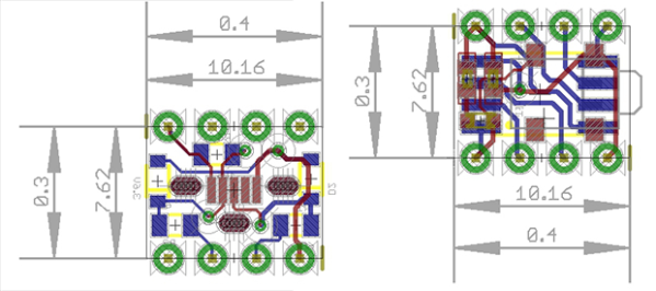
[AtomSoftTech] has thrown his gauntlet down and created an even smaller ‘tiny85 board. it measures 0.4in by 0.3in, including the passives, reset switch, and USB connector. To put that in perspective, the PDIP package of the ‘tiny85 measures 0.4 x 0.4. How is [Atom] getting away with this? Cheating, splitting the circuit onto two stacked boards, or knowing the right components, depending on how you look at it.

USB 
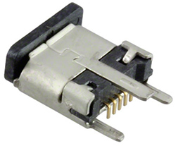
[Atom] is using a few interesting components in this build. The USB connector is a surface mount vertical part, making the USB cord stick out the top of this uC board. The reset button is extremely small as well, sticking out of the interior layer of the PCB sandwich.

[AtomSoft] has the project up on OSH Park ($1.55 for three. How cool is that?), and we assume he’ll be selling the official World’s Smallest Arduino-compatible board at Tindie in time.

How To Reverse Engineer, Featuring The Rigol DS1054Z

For a few years now, the Rigol DS1052E has been the unofficial My First Oscilloscope™. It’s cheap, it’s good enough for most projects, and there have been a number hacks and mods for this very popular scope to give it twice as much bandwidth and other interesting tools. The 1052E is a bit long in the tooth and Rigol has just released the long-awaited update, the DS1054Z. It’s a four-channel scope, has a bigger screen, more bells and whistles, and only costs $50 more than the six-year-old 1052E. Basically, if you’re in the market for a cheap, usable oscilloscope, scratch the ~52E off your list and replace it with the ~54Z.

With four channels of input, [Dave Jones] was wondering how the engineers at Rigol managed to stuff two additional front ends into the scope while still meeting the magic price point of $400. This means it’s time for [Dave] to reverse engineer the 1054Z, and give everyone on the Internet a glimpse at how a real engineer tears apart the worth of other engineers.

The first thing [Dave] does once the board is out of the enclosure is taking a nice, clear, and in-focus picture of both sides of the board. These pictures are edited, turned into a line drawing, and printed out on a transparency sheet. This way, both sides of the board can be viewed at once, allowing for a few dry erase marker to highlight the traces and signals.

Unless your voyage on the sea of reverse engineering takes you to the island of despair and desoldering individual components, you’ll be measuring the values of individual components in circuit. For this, you’ll want a low-voltage ohms function on your meter; if you’re putting too much voltage through a component, you’ll probably turn on some silicon in the circuit, and your measurements will be crap. Luckily, [Dave] shows a way to test if your meter will work for this kind of work; you’ll need another meter.

From there, it’s basically looking at datasheets and drawing a schematic of the circuit; inputs go at the left, outputs at the right, ground is at the bottom, and positive rails are at the top. It’s harder than it sounds – most of [Dave]’s expertise in this area is just pattern recognition. It’s one thing to reverse engineer a circuit through brute force, but knowing the why and how of how the circuit works makes things much easier.

Continue reading “How To Reverse Engineer, Featuring The Rigol DS1054Z”

What’s Next On The Raspberry Pi Front

Raspberry Pi founder [Eben Upton] recently sat in an uncomfortable chair in London to discuss all things Pi. Having sold about four million units over the last 2.5 years, he feels the future is bright for his original vision of inspiring and helping kids to learn programming.

[Eben] is quite pleased with the Pi-Top, a B+ based laptop kit that’s pulling in backers left and right while completely unaffiliated with the Pi foundation. The kit includes a 13.3″ HD LCD screen, keyboard, trackpad, and an injection molded case, though you can print your own with the included STL files. Kits start at $249 without a Pi and $285 with a B+ included. Robot and home automation HATs are also available separately or bundled with the Pi-Top kit.

The most exciting news is that the $600,000 spent on DSI connectors for those four million Raspis is about to pay off. [Eben] hopes that an official touchscreen will be available for purchase before the end of 2014 or in early 2015. He showed off a 7″ capacitive touch panel that will attach to a display board stacked on a Pi, effectively turning it into a tablet.

[Eben] said that they will not be making a Model C and instead are working on revision A+. He hopes to make an official announcement in the near future.

Finally, [Eben] discussed the importance of community, which played a large part in the birth and evolution of the Pi. He also spoke of Pi Academy, a sort of professional workshop for teachers in the UK who’ve recently been tasked with teaching computer science as demanded by changes in the mandatory UK school curriculum. He hopes that these 2-day seminars will help educators achieve the high expectations recently laid out for students to achieve by age ten.

Giving Life To An Undead Baby Doll

If carving a pumpkin this month is too passé for you, take a shot at [Jason Suter’s] instructable and build an animatronic legless zombie child that will surely creep out anyone who has a fear of dolls or other vacant-faced toy babies.

Beginning with a sacrificial doll, [Jason] dismembers all of the limbs and head from the torso in order to make room for the robotic upgrades. The servo motors which animate the new wooden dowel bones are mounted to a chassis cut with a CNC machine. [Jason’s] instructions include some nice diagrams demonstrating how the points of articulation at the shoulders and elbows work in conjunction to produce different flavors of crawling and dragging.

FWFSZPYI0LDVY63.LARGEFFU405MI0LDVY54.LARGE

To top it off, the head is attached to its own mounting plate with tendons that rock back and forth in a miserable undead sort-of fashion. As an added nicety, he explains how to install a bluetooth module into the circuitry so he can tweak and upload his example code to the Arduino brain remotely without needing to get his hands near it. There is of course some additional melting, painting, and doll torture required to achieve that rough-up undead look… but that’s all just icing on top of a well executed piece of animatronics.

In his video [Jason] gives us an overview of his zombie’s build and also shows it in action:

Continue reading “Giving Life To An Undead Baby Doll”

Watch That Windows Update: FTDI Drivers Are Killing Fake Chips

The FTDI FT232 chip is found in thousands of electronic baubles, from Arduinos to test equipment, and more than a few bits of consumer electronics. It’s a simple chip, converting USB to a serial port, but very useful and probably one of the most cloned pieces of silicon on Earth. Thanks to a recent Windows update, all those fake FTDI chips are at risk of being bricked. This isn’t a case where fake FTDI chips won’t work if plugged into a machine running the newest FTDI driver; the latest driver bricks the fake chips, rendering them inoperable with any computer.

Reports of problems with FTDI chips surfaced early this month, with an explanation of the behavior showing up in an EEVblog forum thread. The new driver for these chips from FTDI, delivered through a recent Windows update, reprograms the USB PID to 0, something Windows, Linux, and OS X don’t like. This renders the chip inaccessible from any OS, effectively bricking any device that happens to have one of these fake FTDI serial chips.

Because the FTDI USB to UART chip is so incredibly common,  the market is flooded with clones and counterfeits. it’s very hard to tell the difference between the real and fake versions by looking at the package, but a look at the silicon reveals vast differences. The new driver for the FT232 exploits these differences, reprogramming it so it won’t work with existing drivers. It’s a bold strategy to cut down on silicon counterfeiters on the part of FTDI. A reasonable company would go after the manufacturers of fake chips, not the consumers who are most likely unaware they have a fake chip.

The workaround for this driver update is to download the FT232 config tool from the FTDI website on a WinXP or Linux box, change the PID of the fake chip, and never using the new driver on a modern Windows system. There will surely be an automated tool to fix these chips automatically, but until then, take a good look at what Windows Update is installing – it’s very hard to tell if your devices have a fake FTDI chip by just looking at them.

Function Generator With Zero CPU Cycles

No one is sitting around their workbench trying to come up with the next great oscilloscope or multimeter, but function generators still remain one of the pieces of test equipment anyone – even someone with an Arduino starter pack – can build at home. Most of these function generators aren’t very good; you’re lucky if you can get a sine wave above the audio spectrum. [Bruce Land] had the idea to play around with DMA channels on a PIC32 and ended up with a function generator that uses zero CPU cycles. It’s perfect for a homebrew function generator build, or even a very cool audio synthesizer.

The main obstacles to generating a good sine wave at high frequencies are a high sample rate and an accurate DAC. For homebrew function generators, it’s usually the sample rate that’s terrible; it’s hard pushing bits out a port that fast. By using the DMA channel on a PIC32, [Bruce] can shove arbitrary waveforms out of the chip without using any CPU cycles. By writing a sine wave, or any other wave for that matter, to memory, the PIC32 will just spit them out and leave the CPU to do more important work.

[Bruce] was able to generate a great-looking sine wave up to 200 kHz, and the highest amplitude of the harmonics was about 40db below the fundamental up to 100 kHz. That’s a spectacular sine wave, and the perfect basis for a DIY function generator build.

Cheap Quadruped Robot

Baby Quadruped Robot, Learning To Walk

We’ve all seen videos of those crazy Boston Dynamics running quadruped robots that can reach up to 28 mph. Those things are amazing and it’s almost impossible to imagine how to even start building one. [Max] loves his robots and wanted to build a quadruped but, being a robot hobbyist, didn’t have the serious cash needed to make an extravagant robot like those of Boston Dynamics. Instead he started bridging the gap by designing a quadruped robot that is a little bit slower and tons cheaper.

quadruped-joint
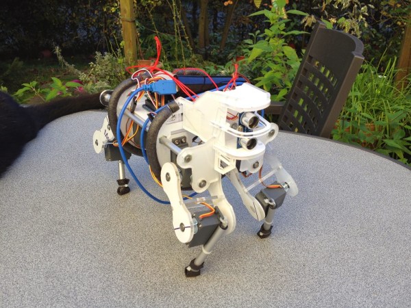
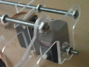
[Max] designed all of the mechanical parts himself. After weighing the advantages and disadvantages of different materials, he decided that the frame would be made from 5mm acrylic sheet. The main body of the robot has acrylic ribs that are spaced apart by threaded rods. Twelve RC servos make up all of the joints, 3 in each leg. Notice in this photo how there is one servo that immediately rotates another servo. To support the other side of the rotating servo, [Max] epoxied on a T-nut, stuck in a short length of threaded rod which is then supported in the frame by a ball bearing. Simple and effective! The upper portions of the legs are also made from acrylic sheet and the lower legs are from a cheap camera tripod. Rubber feet ensure a slip resistant stance.

All of the servos are controlled by an Arduino Mega. [Max] is currently writing a sketch that will perform the complex math and determine coordinated servo motions for movements us humans take for granted, like ‘walk forward’. As you can see in the videos, [Max’s] robot won’t be catching the Boston Dynamics’ Cheetah any time soon but he is off to a great start.

Future plans for this project include bluetooth control and integrating the ultrasonic sensor proactively installed in the ‘head’ of the robot. Check out the videos after the break. [Max] is looking for some feedback on his project. We here at HaD think this needs a great name. Let’s hear some suggestions in the comments…

Continue reading “Baby Quadruped Robot, Learning To Walk”