It’s easy to tell from this process documentary that [Nagyizee] is not one to settle for prefabricated anything. He could have just bought some off-the-shelf DSLR intervalometer, but that would mean interfacing with someone else’s design through cold, soulless plastic.
[Nagyizee] wanted a one-of-a-kind tool built from the ground up. In addition to a timer, he was in the market for a light sensor and sound detection. He chose an STM32F100 ARM Cortex M3 running at 8MHz in the name of power efficiency and started designing the UI and firmware. A custom graphic library for the OLED display streamlines it even further. Once the schematic was finalized, [Nagyizee] devised a stylish and ergonomic wooden case to be milled with a tiny Proxxon F70.
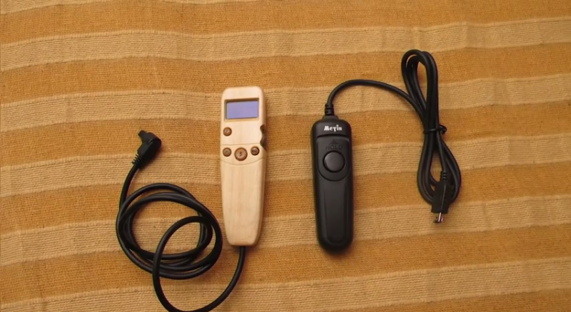
With the enclosure decisions out of the way, he etched and drilled the PCB and placed the components. The light sensor needed a lens and a prism, so he made one from a 10mm LED body. Not one to miss a detail, [Nagyizee] also turned some buttons, hand painted them, and made a scroll wheel. He ends the video with a demonstration that proves it is quite capable. In addition to standard cable release mode, it handles long exposure times, sequential shooting, and capture on light, shadow, or sound. But wait, there’s more: [Nagyizee]’s creation combines modes with ease and grace.
[Thanks for sending this in, Martin]


That’s some ridiculously neat and well-thought out work. If it wasn’t made of wood, I’d have thought it’d just come out of the factory. I’m amazed at how much thought’s gone into what is, in essence, a relatively simple device; A lot of people (including me) would have just thrown something together with an arduino or something, and called it a day, not thinking about stuff like power consumption etc. I like the fact that he’s remembered the battery door; I’ve noticed that’s something that often gets forgotten when people make stuff. Just a bit of a shame it’s not open source, and he’s no plans for production.
It’s a great video for showing the process, too.
Wow, that’s phenomenal work. Well done. I’m curious what tools were used for the physical modelling.
Well done! (That’s not a hack, it’s a prototype…it could go commercial from here.)
I like his 100% approach that went far beyond a Breadboard PCB. Really motivating to see.
I still can get around the fact that he managed to mill his own optics out of an LED. just wow.
Really amazing. Great work and process on the design. Please don’t tell me this is a young kid. LOL…
This is stunning. A one-man engineering, design, and manufacturing firm. I look forward to all of his future projects.
Wow, not only is the project amazing, you took the time to give us a detailed look at how you built this project. It would be interesting and instructive to give a look at all the wrong turns, goof-ups, and lessons learned from this project (so we might be able to avoid them). I usually have to build a project twice to get it right once.
Building twice to get it right once really isn’t a bad average. In commercial projects I’ve observed or worked on, I’ve never seen the “rev 0” board make it out the door. But from what I can see in the video, Nagyizee really enjoys the whole process, so every step is in one way or another computer simulated before committing to hardware. He also takes a “no compromises” approach that would be totally unsupportable in a commercial product, like making the thumbwheel for the rotary encoder, and milling a light pipe for the light sensor. I’d like to see what that rotary encoder looked like before the mod.
And THEN, using solder mask on a home-made board is an amazing beyond-the-call refinement. But wait — no plated through-holes? No silkscreen? Just kidding.
And just when it couldn’t get any better, the fit of the battery door was almost too good to be true. Just the same, I don’t see any claims that no blue wires were used in the making of this project. What counts isn’t getting it right on the first try, but getting it to work like you want it.
Very impressive build and an interesting video.
Q1: What is this 3D modelling software used here? Q2: What is the solder mask production process? It looks pro!
Q1: Rhino
Q2: It looks like he is using a UV setting solder mask. A bit easier to use than screen printing style masks.
This does sort of makes the price of ready-made version more palatable. If you see all the work to get a well-designed package.
Pity though that all too often commercial options of such utility deices are either missing functions or have weird annoyances.
Addendum: It’s odd that he didn’t use a spray lacquer, it seems to me that would get smoother results.