[Shane] bought a multimeter with the idea of using its serial output as a source for data logging. A multimeter with a serial port is a blessing, but it’s still RS-232 with bipolar voltage levels. Some modifications to the meter were required to get it working with a microcontroller, and a few bits of Python needed to be written, but [Shane] is getting useful data out of his meter.
The meter in question is a Tenma 72-7735, a lower end model that still somehow has an opto-isolated serial output. Converting the bipolar logic to TTL logic was as easy as desoldering the photodiode from the circuit and tapping the serial data out from that.
With normal logic levels, the only thing left to do was to figure out how to read the data the meter was sending. It’s a poorly documented system, but [Shane] was able to find some documentation for this meter. Having a meter output something sane, like the freaking numbers displayed on the meter would be far too simple for the designers of this tool. Instead, the serial port outputs the segments of the LCD displayed. It’s all described in a hard to read table, but [Shane] was able to whip up a little bit of Python to parse the serial stream.
It’s only a work in progress – [Shane] plans to do data logging with a microcontroller some time in the future, but at least now he has a complete understanding on how this meter works. He can read the data straight off the screen, and all the code to have a tiny micro parse this data.


You are not fixing serial interface you are modifying at best breaking at worst.
Why not just use this chip http://www.mouser.com/new/maxim-integrated/maximmax232/?gclid=CL30hr76rsICFZPm7AodkU8AVQ on the microcontroler and make ti RS-232 compatible.
Hi Lwatcdr,
Why add in an extra part to get ttl level uart when simplifying the original circuit achieves the same thing? It just seems like an added cost with no extra functionality
The added functionality is that you can hook it to a standard PC still.
I get your point, using the chip means you don’t have to butcher the cable. For people just wanting to use a standard usb to serial converter or a microcontroller, all I’m saying is this is one possible way of doing it. Is this the best way of doing it? Probably not, but it does work.
It does work but you also no longer get the optical isolation.
As I said he modified this at best he did not “fix” it because it was never broken to begin with.
As a one off hack for someone that may not have a MAX232 on hand or wants to convert it to USB it is good hack but it is not fixing anything.
He never said he fixed anything that was the author of this hackaday post. Although the argument could be made that replacing an outdated protocol that is difficult to work around with a much simpler one could be called ‘fixing it’ perhaps it depends on your point of view. Of course there is still optical isolation, the photo diode hasn’t gone anywhere its just wired differently. We’ll just have to agree to disagree but in my opinion a modern multimeter using the rs232 protocol with a db-9 connector that a lot of modern computers and laptops don’t have restricts the usefulness of the serial functionality. This hack makes the data more easily accessible therefore it’s more useful imo.
I never said that I was targeting my comment at the author of the hack. My main problem is with the title. As far as RS232 it is still found on a lot of devices and a lot of motherboards still have the ports as an option. They are still so common that USB to serial cables are very common.
As I said there are good ways to do this. If you want to only use this with and embedded device or if you want to convert it to USB but using a chip like the MAX232 adaptor on the embedded side you can hook it to any PC with a serial cable. Any PC with a USB cable with a USB to serial cable, or to your datalogger.
What I believe Lwatcdr is getting at, albeit somewhat unkindly, is that by removing the opto-isolation, there’s absolutely no guarantee that if the meter ends up suffering from some kind of over-voltage that fries the meter, it won’t carry up the chain and fry the microcontroller as well as any PC that may be connected to said microcontroller.
The write up is so badly written that you would expect that the mod removed the isolation or modding the meter. The mod is to the circuits inside the housing not to the transmitter inside the meter.
The meter still optically isolated as the receiver is in a *separate* housing that is mechanically attached to the back side of the meter.
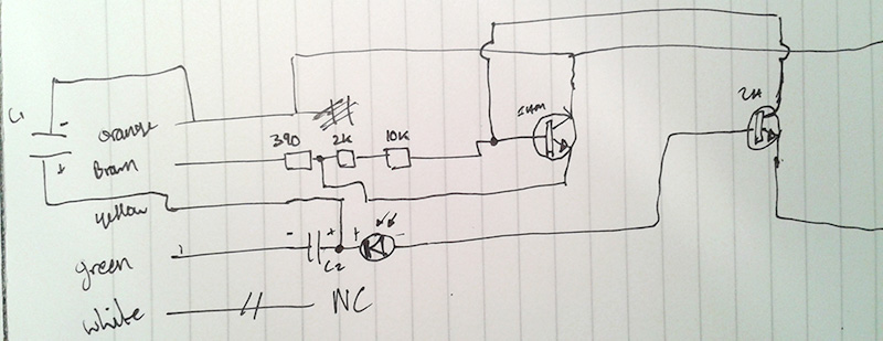
There is a picture showing the simplified circuit inside the housing with the diode and resistor visible as well as a circuit diagram so I’m not sure where the confusion is coming from. also if you have any particular reasons as to why the blog is badly written I would welcome constructive critiscism
I am referring to HaD’s “write up”, not at the blog itself.
Ah ok sorry for the confusion
Well.. if he truly wanted to keep the meter untouched and do things “right” he wouldn’t need just a chip. He would need a DSub connector, a shell a chip and if my quick glance at your link serves me correctly 4 capacitors. He would have to design and etch, or send away for a PC board.
Then when he is done he would have the awkward bulk of not one but two DSub shells, the original and his new one at the end of his cable. All this would have saved him what? An ability he never intended to use anyway.
I probably would have just built up an external RS-232 to TTL converter myself. It would have been even worse than I described because I would have used perfboard, DIP components and put it all in a small project box rather than fit it in a DSub shell. But that’s me. If what Shane did works for him then great!
I guess I didn’t make it clear enough. I do not like the term Fix in the title. I even gave a list of reasons why this modification is a good one.
“What does COM 1-4 Mean? I still have no idea.”
Best guess: they just pump out the internal registers to control the lcd by uart for minimum chip design effort (this would explain why the packet number is in fact just a shift register).
Fun fact: just dumping the LCD control signals per uart adds redundancy / weird form of “checksum”.
It’s a multiplexed LCD, so the separate COM lines (stands for COMMON) are like the select lines in a multiplexer. Pretty common (ha!) in LCDs where you want to minimize the number of SEGment lines used. Otherwise you have one common pin and a pin for every single LCD segment. There’s a balance between multiplexing and contrast since you’re effectively duty-cycling the segments, more COMs mean the time between refreshes is longer. I haven’t seen many go past 4 COM lines but it’s possible.
Thanks for the explanation! Reading the datasheet without that information makes it a bit harder to know what is going on.
I’ve written a decoder for these types of DVMs. I’d sent it to Shane, but can’t find any contact info for him.
Shane, if you’re reading this drop me a line and I’ll forward the program (source code) to you. The decode function is broken out and should be easy to port to your project – save you some time if you’re interested.
on (dot) 9 (dot) okianwarrior (at) spamgourmet (dot) com
You could alway share the code on dropbox or some other file sharing service.
Did that already, must have triggered a spam filter on the site. It’ll appear in a couple of hours.
Yep – took me awhile to find and fix a problem with my dropbox. Here’s the source code mentioned:
https://www.dropbox.com/s/b9q85moc2gql467/DVM.pl?dl=0
This is code for a *different* DVM with a similar interface. It likely uses the same type of interface but with different features. The specs are here:
http://www.repeater-builder.com/radio-shack/22-812/interface-parameters-68424.pdf
The interface is not as simple as decoding the LCD digits. There are weird corner cases such as “SHRT” and “OPEN” in the resistance measurement, “OFLO” in voltage, and so on. The weird cases are per measurement mode, so it’s difficult to make a program that handles all modes.
Also, for logging it’s nice to detect the “m” in the “mV” reading and show the numerical value divided by 1000, and so on. Showing data for logging is ‘kinda involved.
It’s a work in progress – I haven’t tested all modes and accounted for all the corner cases.
Ironically this multimeter ships with software that does the data logging for you on a pc, and has a Opto-isolated RS232 to USB cable included. Files are dumped out in .csv format
I have a Metex 3640D, a DVM with serial output. It came with ScopeView software. I’ve never used the serial port,
maybe it is time to get into it.
Good efforts. All the best for future posts. I have bookmarked you. Well done. I read and like this post. Thanks. http://bestofelectricals.com/energy-meters