[Don] wanted to bring his alarm system into the modern age. He figured that making it more connected would do the trick. Specifically, he wanted his alarm system to send him an SMS message whenever the alarm was tripped.
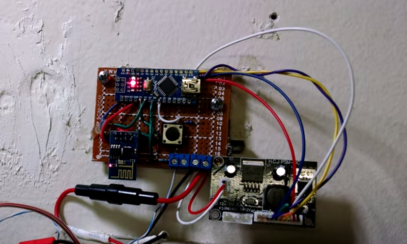
[Don] first had to figure out a way to trigger an event when the alarm sounds. He found a screw terminal that lead to the siren. When the alarm is tripped, this screw terminal outputs 12V to enable the siren. This would be a good place to monitor for an alarm trip.
[Don] is using an Arduino nano to monitor the alarm signal. This meant that the 12V signal needed to be stepped down. He ran it through a resistor and a Zener diode to lower the voltage to something the Arduino can handle. Once the Arduino detects a signal, it uses an ESP8266 WiFi module to send an email. The address [Don] used is the email-to-SMS address which results in a text message hitting his phone over the cell network.
The Arduino also needed power. [Don] found a screw terminal on the alarm system circuit board that provided a regulated 12V output. He ran this to another power regulator board to lower the voltage to a steady 5V. This provides just the amount of juice the Arduino needs to run, and it doesn’t rely on batteries. [Don] provides a good explanation of the system in the video below.


The esp8266 could do this on its own, without the Arduino, correct?
Nicely done.
But why not just use the ESP8266 on its own and leave the Arduino out?
The ESP8266 is perfectly capable of recognizing the input and sending an email.
http://www.esp8266.com/viewtopic.php?f=24&t=1231&p=7329
Then, all you would need is one 3V power supply and one ESP8266 board plus the resistor and zener.
Less to go wrong.
Lets see how much time it would take to re-do this project with just a esp8266.
I know arduino hardware.
I know arduino software.
In a day or two I can have working code on the arduino, and within 2-3 days all the hardware working.
The esp8266 is just a serial device, just add software.
Using just the esp8266:
Download unkown software.
Download unkown compiler, hmmm does this compiler work under Win7 ??? ( NO )
Ok, project will use an arduino.
Most of the same reasons I haven’t started with the eps’s yet. They are amazing devices but are still too difficult for this newbie. If the development continues as fast as it has I will be picking up a couple in a few months.
Not too difficult for newbies, just not worth most people’s time trying to get the setup working when the Chinese company clearly does not care about better docs. They’re probably using the processor’s IP illegally.
For those that are interested in using the ESP8266 without writing custom firmware, check out the node mcu project.
The node mcu firmware will run on any ESP8266 board not just the node mcu one and there are a bunch of windows based tools that make loading the firmware easy. I’m on Mac and just used the ESPtool python script.
You can then program in lua, which has a nice API and is event driven like node.js
The lua API is documented (in English even) and there is a few simple examples, It does lack some more complex “real world” examples though.
Only gocha I have found, so far, is that the pin numbers are remapped.
Now if only my serial adapter would play nice with MacOSX and not disappear every 15min.
I like the project, I’m not sure if you’re aware that you can put arduino software on the ESP8266 now.. (last couple of months)
It’s a piece of cake – definitely would think about it, none of that nasty inconsistent serial nonsense of the stock esp which had varied success on different firmware versions. Just nice clean Arduino firmware, with wifi and without the Atmel chip. there also a few extra funcs this chip can do that an Atmel cant.
https://github.com/esp8266/Arduino/tree/esp8266/hardware/esp8266com/esp8266/tools/sdk
I’m just about to start making a wifi home security system with lots of these little critters. 2 GPIOs are enough for a switch and LED on each of the room-sensors. Chuck in a recursive 4 second sleep timer, and you’ve got a battery operated sensors with a decent life, that can communicate with the base station to report when they are low and need changing.
You can also get esp8266 with 10+GPIO for about £4.
Where is he sending the sms? I get the ESP8266 part with the internet-connection but I dont see any GSM Modem or 3G access board for a SMS.
He mentions in the second video’s text that he uses his phone’s “Email to Text” feature for the SMS conversion.
email to sms address is use its like the phone number @ carriers name.com
I had an alarm panel that was capable of calling the ‘central station’ over a land line for an event (door opened, system armed, alarm, etc). I simply got the installer code (it was left as the default) and reprogrammed the central station telephone number to be the number of my mobile carrier’s voicemail system. Added a few commas for pauses in the right places to match the timeouts for the voicemail prompts and its been sending my numeric pages to my cell phone ever since. Took lots of tries to get the pauses right, but once I did, it never had to be changed.
Using email2SMS feature is nice, but can bring some troubles. For example, if thieves cut off the power, internet connection will probably be lost because most people don’t use UPS or battery backup for their router. So the option with SIM9000 will be more robust because you can power the board from the alarm’s power which probably has some kind of battery backup. Those GSM modules are currently about $20. Bonus is that with a little bit of programming you can add voice feature. When you receive SMS from the alarm system you can “call your home” and listen what is happening inside your house.
Seems too be simple enough without an Arduino, if you try a little…
https://www.youtube.com/watch?v=rVbnnEMDSvU
I would have used an optocoupler to keep the alarm system isolated from the arduino. Also would have used Lua with NodeMCU interpreter on the ESP-01…. it’s much easier and cheaper. No Arduino.
For real simplicity, I think that the 12 volt alarm output could probably power the ESP8266 through a regulator. That way there is nothing to isolate.
The ESP8266 doesn’t have to be powered until needed, so it is safer than relying on a GPIO input still being polled by the arduino a year from now. And the code itself is only an http get or smtp send that happens unconditionally on power up.
I have created a Quick Start web page to introduce ESP8266 and Lua to those who are finding the mass of information a bit daunting and want to give it a go in an hour or two:
http://www.benlo.com/esp8266/esp8266QuickStart.html
That’s brilliant! I’ve been struggling with the WiFi becoming non-responsive on my NodeMCU v3 after a couple of hours. I’ve been working on interfacing this to my Bosch alarm panel by tieing into the 12v siren contacts thinking about an optio isolator (which would have solved the problem of having to pull down GPIO2 with 12v). I can eliminate all this with your suggestion. All I’d need to do is power the ESP8622 through an LM7803 and doctor the code to pull out all references to gpio and just run the IFTTT script. I’m using Noel Portugal’s 1st IFTT Easy Button project. I like the hard coded SSID and key which seems to work reliably.
This gets me around some inherent flakiness in the device. I’m very new at this, only having gotten my NodeMCU v3 flashed yesterday and with minimal Arduino and RPI experience but I think I can probably work my way through the code changes.
Some day these things will become polished and consistent. Till then we do what we can.
Thanks! Paul
This project using an ESP-32 may be of interest…
https://github.com/blaniosh/alarm/wiki