Everyone needs a power supply on their bench, but a standard lab supply isn’t cheap. [ludzinc]’s PSU Console is a cheap alternative, which provides the basic features you’d expect in a lab supply.
The basis of this PSU is a DC/DC module based on the LM2596 step down switching regulator. These modules cost less than a single LM2596, but have all the required components for a buck DC/DC converter. Sure, they might not last forever, and they’re not the most efficient regulators, but the price is right.
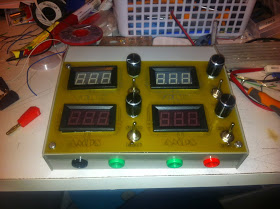
The front panel has four displays for voltage and current, which are just low cost voltmeter displays. The potentiometers are used for adjusting the voltage of the DC/DC, and controlling the current limiter. This limiter monitors current through a shunt, and shuts off a MOSFET when the limit is exceeded.
The final product looks like something that’s ready for daily use, and was much cheaper than most supplies with these features. These low cost DC/DC modules are worth a look if you’re considering a similar build.


On his page he mentioned a thermocouple.
Do you readers have any tips for welding a thermocouple wire at home?
If you mean simply welding 2 thermocouple wires into a single bead, you can do that with a propane or Mapp gas torch by stripping and twisting a couple turns and then heating in the hottest part of the flame.
Haven’t tried that (yet), thanks!
You guys really use a torch?
I worked in a test lab where I took a high current power supply, brought the two thermocouple wires together, then tapped the thermocouple junction against an electrode that effectively shorted power supply through the thermocouple junction.
The result was that the thermocouple junction instantly melted into a ball joint, ready for use. Sometimes it took a few tries to get it right.
Maybe a power supply charging up a large bank of capacitors could be used.
Isn’t that just spot welding, a very common technique?
I used to do it all the time at work using a plain old MAPP torch. I suspect propane may also work, but MAPP burns hotter. I was working with type K thermocouple wire, and the thermocouples were being used mostly in lamination presses for manufacturing.
All you need to do is strip the insulation from the thermocouple wire back about a centimeter, twist the very end together, and then hit the end of the wire with the torch until a small ball forms at the tip. Job done.
I’m sure there are plenty of people out there who will criticize this method, but it worked and worked well. Accuracy was close enough for most applications short of laboratory work (+/- 0.5C).
I welded a thermal couple I got from China that came minus the weld with a couple of 0.8mm mechanical pencil lead and bench supply to a few volts. Took me a few tries to get the hang of it. Make sure you have eye protection for the bright arc.
http://en.wikipedia.org/wiki/Carbon_arc_welding
why do I get the sneaking suspicion this may have been inspired by that bench supply I’v not finished yet….
OP is a well known time traveller
GOLD! You win teh Internet!
Very nice build! I can appreciate the current shut-off, but would it have been possible (suiting this build, analog, no micro I mean) to actually implement a current limiter? That’s one of the best features of my lab power supply I’ve found.
There are modules that comes with constant current. Some even comes with voltage/current display or uC control.
Some of those cheap DC DC modules on ebay/aliexpress do have a second pot for a current limit, so really all you should have to do is buy one that has it.
carefull there, like I learned, they sense the current on the ground rail, and if the current isn’t comming back on it there is no other fallback to do any safty limiting, and your module blows up, and you become unhappy. Your project gets more complex and takes a long time to finish.
(please reffer to http://hackaday.io/project/296-bench-power-supply for details)
Thanks for the warning. One of these might come in handy for a bench supply then:
http://en.wikipedia.org/wiki/Residual-current_device
poly fuses are your friends, build them into all your circuits, because humans are clumsy and can accidentally create short circuits
Poly fuses, like regular fuses, will happily deliver 200% of their rates current for a second or two. Enough to smoke your expensive toys…
If you use a current sense by interrupting the ground then you have to make sure that your supplies are floating. If you need to share a ground, then you need to measure on the other rail.
Using a residual current device or just plain fuses totally overrides the concept of a power supply with current limiting and will result in unpleasant and even frustrating operation.
That current limit works in a different way and because of that you will first discharge the whole output capacitor in your load before it starts to act. Depending on the situation, this might be a really bad thing.
IIRC, Dave Jones (EEVblog) had no trouble incorporating that feature in his power supply design that he made a video series about a few years ago. Of course, the power supply was never finished because it turns out the chips he chose for another part were poorly designed or something, but the current limiter should be applicable in just about any design.
I think that adding the current limit with a linear circuit after the main regulator is a great idea. That way you don’t have to wait for the filtering capacitor to discharge through the load in case of a current limit. However, the pictures show no heat sink on the transistor which means that the supply cannot be used as a current limited supply for extended periods. This, of course can be easily fixed.
I am also worried that the way this is done, the transistor will not be able to be turned on completely at low output voltages.
Does anyone ever bother to hook up a scope to their power supply to see what the ripple voltage is? This is probably a great bench supply for digital electronics but the LM2596 spec sheet indicates that there will be significant ripple voltage. These DC-DC converter modules are very cheap and they might be cutting corners on the components.
One module: 15Vin, 5V 1A out, has a triangular 200mVp-p ripple @150kHz. (Rigol DS1052E).
As expected, nothing special with those 33uH inductors.
Module 2 has an extra output L-C filter. Inductor labeled 3R3, measures as 3.3uH and an elco labeled: “220 35V”, measures as 180uF. (Label “221” seems more logical).
Ouput ripple is (almost) a sine with 80mVp-p @51kHz.
Before the filter it’s triangular 480mVp-p @ 51kHz.
Double checked, but the ic on “module 2” clearly has been labeled as “LM2596”. It seems more likely it’s a LM2576, which runs at 50kHz, or some other Chinese look alike.
On a bit closer examination of “module 1” I noticed the whole surface of the ic has small parralel horizonal lines. Looks like the surface has been ground (lasered?) off, so I don’t really trust the text written on it either.
That seems to be the price to pay for that cheap stuff.
As a novice hacker, is this a necessary as it seems? I can see the merits of having whatever voltage/current you need, but I can get by fine using a power supply I ripped out of an old computer
A decent current limit is often the difference between a led turning on on your power supply or releasing the smoke from your breadboard.
Pick what works for you.
Also, a computer’s power supply is designed to regulate many amps, it might not be so accurate or so clean if it’s only supplying a few mA.
Nope, a computer power supply is designed to regulate some volts and shutdown if the amps flowing are too many.