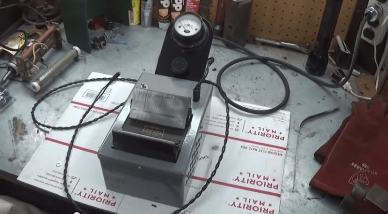
[Mike] has put up a great video on his [SmallEngineMechanic] YouTube Channel about a tool we don’t see very often these days. He’s using an armature growler (YouTube link) to test the armature from a generator. Armature growlers (or just growlers for short) were commonplace years ago. Back when cars had generators, just about every auto mechanic had one on hand. They perform three simple tests: Check armature windings for shorts to other windings, for open windings, and for shorts to the armature body. [Mike’s] particular growler came to him as a basket case. The wiring was shot, it was rusty, and generally needed quite a bit of TLC. He restored it to like new condition, and uses it to help with his antique engine and genset addiction hobby.
Growlers essentially are a transformer primary with a V-shaped frame. The primary coil is connected to A/C mains. The armature to be tested sits in the “V” and through the magic of induction, some of the windings become the secondary coils (more on this later). This means some pretty high voltage will be exposed on commutator of the armature under test, so care should be taken when using one!
Testing for shorts to the ground or the core of the armature is a simple continuity test. Instead of a piezo beep though, a short will trigger the growler to turn on, which means the armature will jump a bit and everything will emit a loud A/C hum. It certainly makes testing more interesting!
Checking for open windings is a matter of energizing the growler’s coil, then probing pairs of contacts on the commutator. Voltage induced in the windings is displayed on the growler’s meter. Open windings will show 0 volts. Not all the armature’s windings will be in the field of the growler at once – so fully testing the armature will mean rotating it several times, as [Mike] shows in his video.
The final test is for shorted coils. This is where things get pretty darn cool. The growler is switched on and a thin piece of ferrous metal – usually an old hacksaw blade, is run along the core of the armature. If a short exists, the hacksaw blade will vibrate against the core of the armature above the shorted windings. We’re not 100% clear on how the coupling between the growler’s primary and two windings causes the blade to vibrate, so feel free to chime in over in the comments to explain things.
Most commercial shops don’t troubleshoot armatures anymore, they just slap new parts in until everything works again. As such the growler isn’t as popular as it once was. Still, if you work with DC motors or generators, it’s a great tool to have around, and it’s operation is a pretty darn cool hack in itself.
Click past the break for [Mike’s] video!


So, he’s purposefully trying to make everybody seasick using nothing but a growler and a youtube. Nifty.
I’d want something similar for testing flyback transformers quick and easy… preferably in-circuit ;)
Wow. If you’re fixing old TV’s and or monitors then how do you get by without a LOPT tester? Half the time the problem is actually in the horizontal deflection. I had a LOPT tester or used a Low ESR meter, can’t remember now.
They are around. You could probably find one on ebay. I would imagine you would have to test with one end of the primary disconnected.
Found some –
http://shop.anatekcorp.com/products/component-analyzers/blue-ring-tester-assembled/?back=products
http://shop.anatekcorp.com/products/component-analyzers/blue-ring-tester-kit/?back=products
Meh, should’ve written SMPS transformers. Offline SMPS are mostly flyback… Thanks for the tip anyway, I’ll look into that!
“Back when cars had generators”. What do they have now? Flux Capacitors?
Alternators.
Since I didn’t know either, I looked it up. A generator is essentially a standard brushed DC motor. The trouble with them was that as the brushes switched polarity, large sparks jumped.
An alternator replaces the brushes with a slip ring. Consequentially, an alternator produces AC instead of DC. Alternators require external rectification and regulation, but since they don’t spark, they last far longer.
Feel free to correct me if I misinterpreted.
http://www.allpar.com/eek/alternators.html
http://www.rowand.net/Shop/Tech/AlternatorGeneratorTheory.htm
Thanks for the links. The rowand website explains for generators that the current they produce is carried by the brushes, while in alternators only the smaller field excitation is carried; the current produced is by direct wiring to the stator.
I don’t like his AC inside/DC outside explanation for generators. I think they just produce DC pulses; the field direction is nearly constant (the rotor turn only a small amount before switching to the next pole) and the rotor current direction for each pole is the same, so the current direction is the same. In the alternator the field is rotating continuously with the rotor relative to a fixed stator, so the result is alternating direction output. In the generator the field is never reversed relative to the windings.
The problem with a generator is the voltage output is proportional to rpm. An alternator’s output voltage is varied through the field coil, so with a regulator you can get a stable(ish) 14 volts at idle or full throttle.
Actually the mechanical voltage regulators used PWM (sort of) to control field current on generators to keep the charging current and voltage in a controlled range.
isn’t it the other way around?
Alternators used commutators to get DC out of the alternator while generators produce AC, the reason being that now we have far more efficient diodes to rectify the output?
Nope, in the automotive world an Alternator is an AC device (often with rectifier and regulator built in), an a Generator is a strictly DC device requiring no rectification.
They’re both AC generators, the difference is whether the rectification is done mechanically or solid state.
Is it just me that laughed at the frequent use of ‘growler’?
P. S. What does the author mean by ‘back when cars had generators’?
Cars these days use alternators instead. An alternator is a generator that creates AC voltage that is then converted to DC via diodes setup to be rectifiers. Generators create DC current and need no rectifiers.
That’s why the “back when cars had generators” comment.
Cheers, I assumed alternator=generator, but I guess in car talk they’re different things!
The hacksaw blade buzz –
What is not mentioned when he is doing the voltage testing is that if you continue testing, going in the same direction after a good pole fails the test then the ones after it will most likely pass even without rotating the armature.
The false fail is not because the pole isn’t between the two test unit formers, it’s because it is at a zero phase point where the induced voltage is zero. So it may also be necessary to rotate the armature for the shorted pole test as well but is far less likely.
Intuitively you may expect that that the magnetism and therefore induced voltage is only being applied to those pole coils that are between the two electromagnetic faces of the test unit however there is another factor.
The pole coils are connected from the end of one to the beginning of the next right around the armature forming a complete loop.
Hypothetically, if you have 30 pol coils then you have the equivalent of 30 (auto) transforms all wound in series because the magnetic field in one pole will induce magnetism into the next pole creating a voltage. The voltage induced in the next pole creates a magnetic field that couples to the next pole and so forth. In this way the induced voltage and magnetism propagates around the armature irrespective of the source point of the magnetism. There are two exceptions. One is at the magnetic null point half way between the two poles of the test unit and the other is the resultant electromagnetic null point 180 degrees from the first.
So (roughly) the resultant magnetism and induced voltage is the difference in phase between the two poles. That is – for 30 poles you have 12 degrees between so the the induction for the pole is delta sine 12 – ie total induction * (sin(angle – 6 degrees) – sin(angle + 6 degrees)).
So if you apply sufficient magnetism to generate a total potential difference of 30 volts then each pole will have 1 volts across it if there are 30 poles.
Unless of course you have a shorted pole. In that case the voltage and therefore magnetic bias across that particular pole will be zero. The electrical short circuit is also a magnetic short circuit.
So for the shorted pole the magnetic difference to the next working pole is far greater than delta sine(phase) which causes far greater interaction with the hacksaw blade. ie the buzz.
Some of the above is not strictly true because for the math to be correct you have to apply voltage or magnetism across one single pole or at 180 degrees apart across the armature however for the hacksaw blade test the effect is the same.
Good god, I nominate this for “most informative comment on Hackaday, ever”. Is there a “Report comment so it can be included in the main article” button? :-)
I remember these things. Grandfather still works with old school generators and has one. They can also test starter armatures for shorts as they are wound much the same as a generator armature.
This reminds me of an experience I had at a yard sale one time. I noticed a growler on the table, and the guy running the yard sale saw me looking at it and said, “I bet you don’t know what that is.”
What he didn’t know is that I spent many of my formative years shadowing my father in a starter/alternator shop.
I don’t do any motor work, so I didn’t buy the growler. It was, however, a memorable experience for me.
Armature growler. Do you see that death metal vocalist singing into your plumbing?
Sorry for off-topic, can’t stand that.
Yeah, makes for a good metal band name as well – The Armature Growlers!
where can we buy armature growler tester and how much is the price