[Blancmange] built a custom door chime using an ATtiny85. Unlike most commercial products out there, this one actually tries to be secure, using AES-CMAC for message signing.
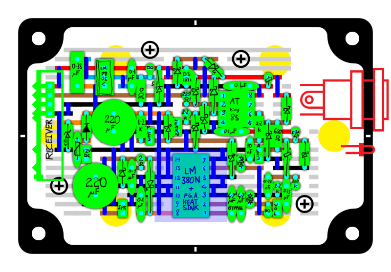
The hardware is pretty simple, and a protoboard layout is shown in the image above. It uses the ATtiny85 for control, with an LM380N audio amplifier, and a low cost 315 MHz receiver.
The more impressive part of the build is the firmware. Using AVR assembly, [Blancmange] managed to fit everything into the 8 Kbytes of flash on the ATtiny85. This includes an implementation of AES-CMAC, an AES cypher based message authentication code. The transmitting device signs the request with a key shared between both devices, and the receiver verifies that the message is from a trusted transmitter.
Fortunately, the assembly code is very well commented. If you’ve ever wanted to take a look into some complex ASM assembly, this is a great project to check out. The source code has been released into the public domain, so the rest of us can implement crypto on this cheap microcontroller with much less effort.


Whoah that is a crazy code !
Neat project. The whole “it was such a tight fit it had to be done in _assembly_!” trope is a bit untrue these days; size-optimising compilers are pretty good, and there’s no reason to expect something like AES-CMAC would take a lot of flash to implement.
And even if it is a tight fit in C, there are plenty of cheap MCUs with bigger flash.
the reason for this projects hack-worthyness is now we can say this:
“Why don’t you have strong encryption for your system? For goodness sake, it can be done on an attiny85, what could your excuse possibly be?
An ATtiny45 is more than adequte. I chose an ATtiny85 for this doorbell so I could squeeze in the four 32kHz sample players, the tone sequencers, the sound samples, the tone and sweep sequence data and the authentication details of up to eight transmitters.
In my experiments with avr-gcc, even with link time optimization it doesn’t come close to assembly.
Look at my picoboot boot loader and see if you could write it in C and still fit in 64 bytes.
“there’s no reason to expect something like AES-CMAC would take a lot of flash to implement.”
There is actually EVERY reason to believe that an assembler version would be much more compact and much faster.
And then of course there is the question of what “a lot of flash” means, what does it mean on an attiny85 and what does it mean on stm32f4?
I didn’t say a flash version wouldn’t be smaller – I said its size wouldn’t be a significant factor. I’m confident I could implement AES-CMAC on an attiny without having to revert to assembly.
Well? We are all waiting. Go ahead.
Do it.
I too would like to see a ‘C’ version of the AES-CMAC part of this code being available.
Here’s the Crypto AVR library that I use so you can see a comparison of C vs ASM – http://www.das-labor.org/wiki/AVR-Crypto-Lib/en
I chose assembly because I wanted cycle-perfect timing for the four voice 32kHz sample player and the Manchester decoder, among other things. AVR assembly is pretty swish. It’s much nicer than the Z80 and the 6502. #include The Four Yorkshiremen sketch.
OK, but what is preventing replay attacks?
Each transmission includes a sequence number. The receiver can track the largest seen sequence number and ignore messages with sequence numbers less than or equal to that value.
Ok for the simpliest replay attack . But with an SDR coupled with a transmitter , you can easily jam the sent frame. The receiver never get this one , and so , does not increment the counter. The replayed frame will be considered as valid . One solution is to use time synchronization (with rtc for example) . But it’s out of subject considered the good job done here ! ;-)
Good point. The most this lets you do is delay a ring, though – if a subsequent ring makes it through, the receiver will update with the higher number, invalidating your recorded message.
You’re right :) I’m a little perfectionist here because it’s a part of my reflexion for an homemade arduino based home alarm !
The jamming desynchronized the transmitter as it would have a higher sequent count than the receiver. I hope there is a synchronization as all the person at the front door would try pressing the button a few times without hearing the bell and give up.
Car locks w/ rotating keys allow X future keys to work until its found because your transmitter will undoubtedly accidentally go off and use of keys in your pocket.
What happens when the sequence number exceeds the maximum number possible? Does the counter start over? This would mean that the receiver would need to register it has reached the maximum number and start over, but if someone managed to jam it during this time, the transmitter would be sending lower sequence numbers and the receiver would ignore it. Correct? This is highly unreasonable to expect, to ever happen, as the switch would fail before that number was ever reached. But was just curious.
Hopefully the homeowner would notice someone pressing the button on their doorbell 4 billion times.
Hahahahahha
More seriously, one way to handle this is for the receiver to maintain a window of values it will accept; this starts at one greater than the last value it received, and extends for some fixed number – say, 256 or 64k. This permits wrapping around the end, but also means that the transmitter and receiver could become desynchronized, requiring a sync before they work again.
The window method is indeed what this project uses. There is quite a bit of complexity in minimising the risk of desynchronisation: The next sequence number for each transmitter the receiver knows is saved often into an EEPROM wear-levelling arrangement, one for each associated transmitter.
Is there a schematic of the transmitter ?
Not yet. The transmitter is presently only running on a tiny 170 point breadboard (with five buttons and two LEDs and all). Apart from the ESD protection measures, the transmitter circuit is pretty simple and the circuit diagrams for parts of it are included in the source code.
Here’s a layout diagram for the transmitter. It’s not yet tested, but apart from all the ESD protection and the BS107 logical-level MOSFETs used as input signal conditioners, it’s not too far from what have running on a 170 tie point mini breadboard.
http://www.realhamster.com/stash/GateBuzzer/transmitter-allthebits.png
This seems a little overkill, especially since he had to use assembly to fit it all into his chip.
A simple LFSR Rolling-Code would have probably worked euqally well and would be much cheaper (flash and run-time wise) to implement.
Additionally there is the point of battery life.
Every instruction the CPU spends on calculating the MAC it uses up your precious mAh.
Depends what you mean by “worked equally well” – it’s trivially compromised. That probably doesn’t matter much for a doorbell, but it doesn’t mean it’s a good idea. And if it’s trivially compromised, why use a code at all? Just send a “doorbell pressed” message.
The power consumed to calculate a MAC is trivial compared to the power consumed sitting in idle mode for 99% of its life.
As for power consumption, the transmitter design is at present rather brutal: It’s busy waiting and all! However, it will use far less power than the enormous beam detector is will be sitting next to, along with the secondary beam detector I plan to build.
When I need the efficiency, I will use Atmel’s more sophisticaed, interrupt-driven design, sleep mode and all. By their reconning, the key fob’s battery’s sefl-discharge is the limiting factor for battery life.
Here’s a YouTube video of me testing the breadboard version of the transmitter and receiver. It begins with putting the receiver in Learn Mode and pushing the Teach button on the transmitter. From there, the sensor inputs (emulated as buttons) are stimulated and the sound Advance buttons (one for each sensor) are pressed.
No shown in the video is the delayed Teach function (so you can share the auto-generated AES keys inside a microwave oven if you want) and the sensor sense reverse toggles (for normally open vis normally closed sensors).
[Let’s try that video URL again] https://www.youtube.com/watch?v=q1R05Dbqx2k
oddly the link on realhamster goes to a 403 error page
Sorry, that was probably my fault. Try it again? If it’s still busted drop me an e-mail, michael@hotplate.co.nz
Hi I was looking for a aes encrypt/decrypt for AVR8 but the link in the article is a dead link. If by chance somebody still has it I’m really interested.