When you think of WiFi in projects it’s easy to get into the rut of assuming the goal is to add WiFi to something. This particular build actually brings WiFi awareness to you, in terms of sniffing what’s going on with the signals around you and displaying them for instant feedback.
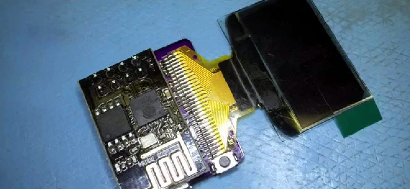
[0miker0] is working on the project as his entry in the Square Inch Project. It’s an adapter board that has a footprint for the 2×4 pin header of an ESP8266-01 module, and hosts the components and solder pads for a 128×64 OLED display. These are becoming rather ubiquitous and it’s not hard to figure out why. They’re relatively inexpensive, low-power, high-contrast, and require very few support components. From the schematic in the GitHub Repo it looks like 5 resistors and 7 caps.
The video below shows off two firmware modes so far. The first is an AP scan that reads out some information, the second is a weather-display program. Anyone who’s worked with the ESP modules knows that they have the potential to gather all kinds of data about WiFi signals — one of our favorite demos of this is when [cnlohr] used it to create a 3d light painted map of his WiFi signal strength. Chuck a rechargeable LiPo on this thing, tweak the example code for your needs, and you have a new gadget for wardriving-nouveau.
Looks like there’s already 29 entries in the Square Inch project which we mentioned earlier this month. You still have time to start your design… add it to this weekend’s list of hacks.


About 9 months ago I built something similar, back then I needed an arduino attached to drive the display via I2C (https://github.com/bennyborn/uMessenger). I discovered that project a week ago and instantly ordered some boards from OSHpark for myself to tinker with them. I really like the idea of having such small displays easily hooked up to wifi :)
Not much the the schematic really. Just a power supply, display and and ESP but you could any type of data you want and display it. Time of day, Wifi info, possibly mail or tweets…
the main problem with the small oled displays is that they wear out over time. their on-time is something like a year or two and after that they start to fade (according to their specs).
also, you can find 2 general types: i2c (4 pins) and spi. if you need faster drawing speed, definitely go for the spi version. on some motion gfx I did, the spi one was about 4x the speed of the i2c common versions.
The object life can be greatly expanded by sending display to sleep, or add a proximity sensor to light up just when there is movement.
agreed.
that, and I prefer to make it easy enough to swap in new displays by not soldering them down and socketing them, instead.
I hear they deteriorate over time. I’ve had a desktop clock with the same oled display running for over a year now and it’s still ok. Looks a bit dim so if it gets worst them I’ll just replace the glass.
SPI is crazy fast compared to i2c. Check out my test: https://youtu.be/SvOX-xs9v8M
Cute & useful!
That’s a great project. I just picked up a few esp8266’s to play with. I thought it would be fun to scan and log all networks I pass through on a normal day. I’d like to pair it with GPS data but hadn’t thought of adding a screen.
Long ago I repackaged a GPS Board that uses the same display. 99% of the code is used up so adding a wifi module would be tricky: https://youtu.be/vVtMzm-KlI8
I’m impressed! A 30-pin ribbon cable all neatly soldered down and it’s still using I2C.
Ah, the (cheaper) I2C, PCB mounted one takes you over the 1-square-inch limit. Okay! :-)
The same glass is i2c or SPI depending on what pins you use. the ESP-01 only has two I/O so SPI was not possible. After soldering a bunch I can now do it in 10 seconds. Just tack down the middle and edges, then use plenty of flux and wipe your tip coated in solder from right to left. Wasn’t so easy at first though.
Is there any epaper screen of similar size and price as that OLED?
i’m working on a similiar project with the esp8266, i have a simple prototype up and running with the oled display, i found cheap (~$8 US on alibaba) epaper display with an SPI interface GDE021A1. (http://www.good-display.com/downloadsfront.do?method=picker&flag=all&id=cbf74932-4964-43d6-9f0c-d1c45feaec77&fileId=b77fe515-0642-41b3-bd92-fafe23327233)
thank you. I hope you submit the project when you’re done. I’ve seen some stores use epaper (or maybe lcd but I think epaper) on shelf price tags now. I wonder if one of those would be easy to repurpose for some other project.
Those have been featured on hackaday a couple of years ago, they got reprogrammed in the supermarkets by flashing of lights if I recall! Pretty neat.
I found http://hackaday.com/2014/05/03/game-boy-vs-electronic-shelf-labels/ which might be the article you’re thinking of. I see such shelf tags in more and more stores. A large supermarket can have loads and loads of them. I wonder if they can be easily repurposed as a notification screen for a raspi or some such. To display temperature data or some other short message. It is easy and inexpensive to get raspi to send IR.
I’ve never used epaper but love the idea of it being readable all the time while using little current.