You have to admit [Dylan Rush’s] clock is a real swinger. Literally. You’ve seen the desk novelties where an arm with leds mounted on it sweeps out a message? [Dylan] did the same thing to make a clock but instead of drawing numbers, he actually draws an analog clock face. Y’know one of those round things with arms?
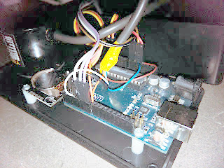 Behind the clock is an Arduino driving a MAX7219 LED controller. Using the MAX7219 was a challenge because it expects a grid of LEDs while the clock needs a linear array. [Dylan] used a line of individual LEDs wired to match what the controller wanted. A rotary encoder tells the processor the position of the arm so the Arduino sketch can determine which LEDs should be lit to show the time and clock face.
What’s even more amazing is [Dylan] created this before clocks became infamous.
Swing over to the video after the break.


At first I thought is was a crappy video, I thought the front of the pendulum was reflecting overhead lights.
I guess I was expecting red LED’s.
This is too cool. I want one that is integrated into a Kit Cat clock.
+1
If those Clocks For Social Goods on hackaday.io would be a contest, I’d give up right now. This one wins. Awesome!
Oh, and I forgot: this needs to be a kit.
awesome idea and application. need see night or darkness.
When I saw the teaser gif, I thought this was the dumbest idea ever. There isn’t enough persistence of vision to determine the time. The real video does a much better job showing just how this build looks.
I now know that it’s not the project but the damn animated gifs that makes it look like crap.
The project is really cool. But I probably would’ve wanted the pendalum to swing on its own. A nice touch would be to move the cord behind a half tube to make the package a bit nicer.
I like how he multiplexes the LED’s manually with enamelled (magnet) wire and then uses crappy Chinese hookup wire for the flexing part. Nicely curved magnet wire would handle the constant flexing for a long time but the hookup wire wont last long at all. The solution is to put *everything* on the pendulum and just have power going through the pivoting point.
Great build, I actually like the fact that the movement is not powered and you or someone else has to move it to see the time.
I wonder if the math for converting radial coordinates to arc coordinates is done by the Arduino or if that part of the math was pre-computed and loaded in as tables.
I just looked in my junk bin and I don’t have enough Red/Green or Red/Green/Blue LEDs or I would be starting this now lol.
The two PIN Red/Green LEDs would be easy to work with for a small DIP micro.
go all out and make a 1 meter long ws2812 version.
I am in the process of making two clocks with neo-pixel rings. I don’t really think you need lots of colors. The Two color LED’s will give Red, Yellow and Green or a range from Red to Green. It’s much easier to have 16 wires for 64 x 2 pin bi-color LEDs than 32 wires for Red, Green and Blue.
With the three color LED’s you could put up a CGI image of a real clock in perfect color but like I say, it’s too many IO pins for a Small DIP uC.
A longer pendulum would help to, with the image towards the end.
I had a think about making one and what is ‘key’ that this project has nailed is the position sensors resolution.
I was thinking of having everything on the back or inside the pendulum so that a simple brush and ground conveys the power through the pivot point (and position sensor). Just turn the world back and forth instead of the pendulum and use a high resolution rotational sensor to detect the current position of the world.
It took me a minute!
This one wins the Internet.
This is an awesome, and yet simple. work of art.
Bravo :-)
Wish I had done something so effing cool!
Doesn’t the 7219 actually expect 8 7 segment displays?
7 Segments *and* a decimal point to make up the 8th.
Minor quibble – pendulums only keep accurate time when the arc is small (in the region where sin theta ≈ theta).
Your suggestion is completely dependent on the units for theta Pi (w), Radians, Gradians, Degrees.
Did you mean ‘where sin theta ≈ cos theta’ ?
No, he’s talking about radians. https://en.wikipedia.org/wiki/Pendulum_%28mathematics%29#Small-angle_approximation.
Ok. man: where sin theta ≈ k theta. Happy?
Yeah, but he doesn’t use the pendulum to measure time. Timekeeping is done via DS1307 RTC.
This is a pretty cool idea. What he needs to do is put a small electro magnet on the end so when he starts it swinging, it keeps the momentum going. He could use the rotary data to kill the coil right as the pendulum passes over. Similar to those little solar dancing toys people have in their cars.
Usually they place the magnet or the coil at the lowest point of the swing as it is independent of the magnitude.
I wonder why the border of the led strip is that color. Seems an odd choice.
It would be at the bottom of my list of choices.
And at the same time the stationary box is black and is unappealing against that wall and with that wobbly wire and all.
This is in urgent need of a visual design makeover.
But I like the novel idea.
I believe the border strip is unfinished wood.
It’s obvious what the box is.
But yes, the project is cool but v2 needs to focus on aesthetics. Then he would have a real winner on his hands.
You are right of course, it’s the color of the wood (plywood I’m guessing?) it’s made of.
Stupid that I didn’t realize that.
Needs improvement though.
sure this is a clock? looks like it could burst into pieces and kill people!
i wanna build one right now!
The specs for the encoder that everything is pivoting on is
Allowable Radial Load: 5N (~500g)
Allowable Axial Load: 3N (~300g)
So I would hope the wood is lightweight balsa wood.
This also means that powering the movement would be extremely difficult. Perhaps a magnetic cage like the head drive for a hard disk.
I thought about making a powered movement that was longer but the sticking point is the encoder. The one he is using is a $40+ encoder with about 1000 pulses per rotation which gives him a resolution of 3mm on the furtherest led (worst case).
I found 600 pulse per rotation encoders on ebay for $15 but the resolution doesn’t cut it and especially so with a longer pendulum. I was looking for alternate encoders that will hold more load and a powered movement system.
I wonder if you could use two encoders and rotate one a tiny bit to get a double precision. It should be possible I figure.
Or just use some sort of gear system to translate the 360 degree (or close to it) of the encoder to the 90 or so degrees a pendulum moves through. I’m sure doing such has been done before and that there are patents describing such a setup.
I’m tying to think of a way that integrates the drive and feedback. I have probably given up on rotary encoders as they’re bulky and have no rear bearing so that are a weak point and poor resolution where it counts.
I wanted to use a real pendulum ‘as in’ about a meter long that has a two second period. Wear is a consideration for this constant movement so a shaft with *two* bearings would be needed. All the components including the drive can go on the pendulum so that the fixed point is just a pivot (shaft lock) and one brush to convey power as the shaft can be the other voltage polarity. This would make the pendulum the only moving part and the only three contact parts are two bearings and one bush.
The problem is that a very high resolution is needed to get down to the diameter of a LED at a distance approaching 1 meter.
I thought about just using timing and then the uC only needs feedback from one or two ‘off center’ points. This can be done opticly from close to the pivot with some calibration in the software. But to do this I need to compensate for the fact that the rotation offset vs time is non-linear.
If I make the drive to offset wind resistance so that the drive is max at center where speed is max and drive is min at full offset then the calculation would be quite simple. Using full balsa wood and rounded edges would also help.
Maybe I can use a HDD platter motor if they have some feedback. A CD spindle motor was three drives so perhaps I could use two for left and right and sense with a analog input on the other for position. Even the 3 pole delta quadcopter motors would do in a pinch. What ever can give feedback. I will try a couple of motors from the jusk box like cd/hard drive motors and see if anything has a usable torque to smoke ratio.
I see your point, and it will be interesting to find out a good way to do it I think, but as for that rotary bearing issue, if you just extend the shaft and put two bearings on that with the load on the middle it would not need a rear bearing on its own since the actual encoder would only experience rotation.. But you’d still have the wear unless it was optical. And I think something else might work better, and surely the time although not linear is constant per swing and you should be able to get it going by just knowing the key values and determine the rest mathematically, or even with a table of delay values if running the math is an issue.
Anyway, I think with some deliberation you\d come up with an answer.
Old floppy drive steppers? Just need to add a couple of comparators and you can use them as quadrature encoder. Or you can use it to give the kick to the pendulum as well as encoder.