It looks like [Michel David] and his team at volumetrics.co have really upped their game: the game being production of a 3D volumetric video display.
We’ve covered an earlier version of the same technique, and still the best technical explanation of what they’re up to is to be found at their old website. But it’s a simple enough idea, and we expect that all of the difficulty is in making the details work out. But if you look at their latest video (just below the jump), we think that you’ll agree that they’ve ironed out most of the wrinkles.
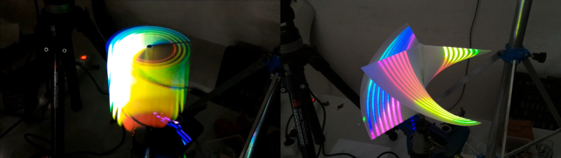
The newest version uses a standard overhead projector (“beamer” in “German”) to project images onto a rotating helix. By changing the image rapidly in sync with the rotor, you can choose how high up the corkscrew the light beam hits. Spin the rotor around (on a Dremel!) fast enough and your POV takes care of the rest. We really like the simplicity of the current setup, and the results speak for themselves.
Doing the math to figure out exactly where and when each point of light should be projected is no mean feat, but if you’ve got a very accurate model of the helix, it should be possible. And that makes this a perfect excuse for a big 3D printer — you can ideally make a helix model in your computer and then print out the exact same shape.
We’d like to see a lot more detail about the newer version, and maybe a link to some of the software. And we’ve still got one nagging question: how do they get the sync right between the spinning helix and the video display? We can’t see any rotation sensors or feedback. Is it just tuned?


If they manage to get the wobble out of it (bracing the unsupported end), it would look a lot sharper.
Any brace they put at the top would block the light from the mirror/projector. The image started out stable then became more unstable over time. Maybe a balance issue or the structure coming apart over time? Maybe a machined aluminum helix?
Print it with the helix overlaid on a cone like a prop. Weight the bottom like a flywheel.. the top of the cone wont wobble as much
They just need a shaft that’s rigid and long enough on the opposite side and something to support it. The core of the helix would need to be thicker, though, I think. At least on one end.
they should coat the under side of the helix with a non-reflective paint
No need to sync if you want to display prisms. The beamer project a constant image.
“we’ve still got one nagging question: how do they get the sync right between the spinning helix and the video display?”
Answer: They don’t. Not yet, anyway. You can tell because everything they are displaying has no variation in the vertical axis which is all that would need that sort of synchronization.
To make it synchronized they will have to rotate the helix at exactly 60 times the frame rate of the projector which they might make work with feedback that compares an rpm pulse to the vertical blanking interval and drives the motor with the error signal, just like a PLL.
damn.. its a scam. not a hack
It looks like they have a photocell or something mounted next to the Dremel for sync. Not sure if they’re using a laser or just the projected light for a source though. This will be really impressive with a purpose built rig using a proper spindle motor and a little better balance on the rotor. I wonder if you could mount the projector below the helix and use a magnetic bearing or something for a really seamless presentation…
Yeah, that’s cool! I like their earlier volumetric display concept better, though. This new one only shows extrusions, at least, until they figure out how to get a high-speed display. The old one showed non-extruded 3D info, encoded into a “slice wheel” — https://thecriticaltechnologist.wordpress.com/audiovisual/ I really like their explanation and site.
—me
>
this reminds me of the Voxiebox. I think the Voxiebox is cooler, but I haven’t ever used the helix displays, so I’m biased. http://www.voxiebox.com/
Interesting alternative take on the same basic concept. The demo videos taken in the dark look cool, but the Voxiebox looks a little awkward with the lights on:
https://www.youtube.com/watch?v=jd1OHItXz9s
I don’t think a linear mechanism will hold up as well over time as a rotating display.
That’s nice.
I think every 3d projection needs a proof of concept rule to perform the Leia hologram.. ;)
Help me obi-wan kenobi, you’re my only hope..
The math for calculating “real” 3D objects (as opposed to the extruded 2D shapes on the video) could be very tricky and you’d probably need a much higher refresh rate on ze beamer.
Also that fast-rotating helix probably generates quite an airflow that probably adds to the wobblyness of the structure.
The math isn’t so complicated. But a video refresh rate in the 10s of kHz would be needed for high quality 3D.
Airflow I expect could be reduced by a flat plate at the bottom of the helix. Wrapping the helix in a cylindrical window would then cut airflow to almost nothing.
“Airflow I expect could be reduced by a flat plate at the bottom of the helix. Wrapping the helix in a cylindrical window would then cut airflow to almost nothing.”
Physics 101 fail. If you obstruct the airflow you increase the air resistance of the helix and effectively reducing the maximum speed you can achieve (for the same motor power).
Unless you suck out all the air!
If you block the flow of a centrifugal fan, the motor goes faster due to a decreased load. Try blocking a wet/dry vacuum’s hose. You can hear the speed of the motor increase. Mathias Wandel has a video about this.
I would have thought you need a full frame refresh for each line of z-axis resolution, and synchronised projection (beaming) with projector change.
Call it 18Hz (beginnings of POV) into 120Hz (high-end 3d projector refresh rate) gives you 6 lines.
And then you’d lose xy clarity and size because of not spending as frequent visits of the screen to each voxel. Or you could project from inside the helix, back-project, and have an easier time with less depth.
Now, make a much larger zoetrope, put a greater number of fins on it and sort the timing, and you’ll get there. Only just safer than lasers and exploding air.
Helix and a projector. This was done first when this guy was in diapers.
How would one have the projector (“beamer”) compensate for the variable focal distance to helix? It seems like most of the volume would be out of focus.
I could be way off, but if using a laser projector, that wouldn’t be an issue. I remember seeing a story here about a guy that did a “3d display” with a spherical light bulb protector “dome” that used a laser projector to compensate for the variable distances…
Using lenses. You use a wide-angle lens to expand the image to the correct size, then immediately have it go through a magnification lens which directs the correctly-sized image into a consistently sized beam.
Yesterday ot was “C”, today “German”. So the [name] thing has a new variant for “languages”.
Thanks for the great feedbacks, we will try some of your ideas…
As for the synchronization of the Helix to the projector, in this prototype there is no sync. We wanted to test the 3D printed helices quality, and most importantly make it simple for anyone to make.
Michel, please fix your “Get news and updates” sign up button–nothing happens when I enter my email address then click on it.
Also, “We want you to build your own volumetric display by either printing a helix using our downloadable file…” Could you please post a link to the download? I don’t see it on your website.
You should klick on the 3D player, here’s the link:https://sketchfab.com/models/3d18511017304afaa2ed031810a4705f
I’m guessing that it looks better in person, without camera frame rates screwing up the image. So, my only choices are to visit Germany or make one. But one major thing not mentioned in this article, which you won’t discover unless you click through the link to the Volumetrics website, is that they’re ???????????????????????????????????????????? you to make one.
Gotta book some 3D printer time at TechShop…
Except, Volumetric’s “Sign Up” button doesn’t work…:-(
Help me Obi Wan Kenobe.
Princess Leia was linear enough that it might work.
quick! someone talk me down here and tell me again why I don’t need a good 3D printer! :)
Because there are lots of services that will do your 3D printing for you. Or you could join a makerspace.
Spare projector? Check.
Access to a decent 3D printer? Check.
Spare mirror? Check.
Spare motors? Plenty.
I’m going to try to replicate this. I’ll report back with my results.
Your checklist is missing 10 rolls of filament. It seems unlikely that the print will work on the first try, given the slopes on the helix.
I worked on the US Navy’s experimental 3D volumetric display.
We used NEOS accousto-optical devices to steer the laser in the X and Y into the volume occupied by a two-bladed helix machined from a solid cylinder of aluminum 13 inches in diameter.
Because of a limit in the time it took the Bragg diffraction grating to settle down to a new value of deflection, and the fact that we were going for a 20 Hz refresh rate, we were limited in the number of voxels we could display per frame to about 40,000.
The software was written in C++ in 1989, using the Zortech C++ compiler, and the code ran on a 40MHz 386, talking to an ISA board designed in the lab that held the buffers for driving the X,Y D/A converters that drove the RF modulator that drove the crystals in the AO devices.
The math was absurdly simple for this device: The Z axis was slices of time, and we got an interrupt when blade 1 crossed through 0 degrees.
This is awesome! I was reading about you guys.
Thanks for the great insights, it must have been fun to work on this at such early stage, much place for inventiveness.
This reminds me of the helical mirror system used in early, early television, only in reverse, as a scan is projected onto the helix rather than the helix creating the scan.
This is great stuff, thanks for the reference