Inexpensive bench top power supplies are great for the home hobbyist, featuring wide voltage range and current limiting for a low price. What’s not to love? The controls; most have a single-turn pot that is typically very fidgety, especially at low voltage.
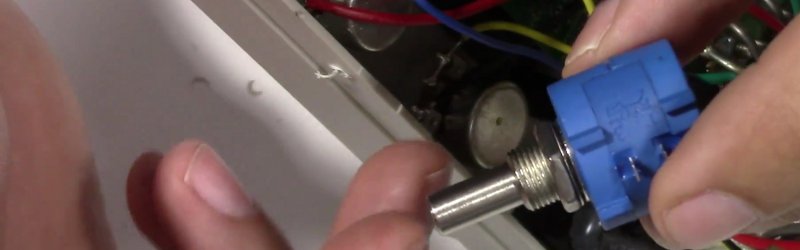
The solution is to replace the factory pots with nice wire-wound 10 turn units in order to gain 10x the precision. Of course nothing is ever drop in, the new pots didn’t fit the old holes, but that is nothing a few moments with a drill can’t fix. Also the original knobs no longer fit, but that’s just an opportunity for a knob upgrade.
The end result is still a power supply with fidgety controls, but instead of holding your breath, tippy tapping knobs to get within 100mV of your target, you can dial right in to within 10mV of your target. That makes life much easier, especially on low voltage projects that may not have power regulation quite yet.
Join us after the break for a video with all the info.


I’ve done similar mods many times, from the voltage set pot on several old HP 721A power supplies to the frequency vernier on an HP 8640B sig gen. The 10 turn pot gives much better resolution than a single turn. Good hack.
Doc
I’ve done exactly this mod to my 721A, never thought about performing the same hack on the 8640B, though! Thanks, Doc!
I used the same 10 turn precision pot on an adjustable DC-DC converter. Using a switch mode 24V PSU (wound up to 27V) and then then two adjustable DC-DC converter made a great, cheap dual channel CC/CV lab power supply.
Simple and highly effective. Good Hack!
A word of caution:
A wire-wound pot can have significant inductance, and thus may introduce odd regulation effects, especially with sharp transients.
Excellent point. I came here to state the same, in addition to the fact that wire-wound pots can exhibit significant variation with temperature. HaD really needs to step-up it’s game and add some value to their posts, not just reflect what’s found.
A good mod that I’ve done several times. I have always hated the cheap power supplies with a two pot system, coarse and fine.There are some rather expensive power supplies that are cheap in that regard.
You know, what’s worse: A coarse/fine coaxial pot with loose wiper contacts. And when they lift off due to vibration you have a transient of full voltage of the electrolytic smoothing cap on the output, something like 30 to 40V on 24V max. PSU. And “bang” goes the newly built, tested and adjusted circuit. :-(
So I replaced the pots with 10 turns and added nice 10 turn dials with mechanical numeric readout. And a fan regulation, because originally it only switched between “loud” and “very loud” even at no load.
It gives you finer control (i.e. resolution) and not necessarily an increase in *precision*.
uh… if you went to all that trouble, just replace the knobs with digital pots and stick a micro in there and you have a programmable supply
Easy to say, instead of saying how someone else should have done it. Do it yourself.
uh…no. Swapping a pot for a 10-turn is as simple as unsoldering and resoldering three wires. What you are suggesting involves much more engineering effort (if you want to do it correctly) and “sticking a micro in there” is almost certainly not going to work. You’ll find that out when either your power supply or the project you’re powering from it begins to smoke.
Especially as the micro wants to be programmed to do anything useful, whereas analog hardware does not have this problem. That’s the reason the fan regulation I added to my linear Lab PSU (additional to the 10 turn mod) does not contain any µC but a zener diode two transistors (TO-126 case) and some passives. One of the transistors is the temp sensor, the other is an emitter follower. The only “programming” I had to do was adjusting a trimpot and instead of a compiler I could use LTspice. :-)
Plus, there may be another subtle problem with digital pots. Some digital pots have an internal clock that runs continuously as long as there is power; some others have ROM and use no clock (apart from the one required by I2C or SPI, which can be deactivated after the pot is adjusted and is in use). You may want the latter variety in high-precision applications, the ones with the ROM, which you can adjust and forget, because the former variety may inject unacceptably high clock noise.
I love ten turn pots. I always pick up ones I see at ham fests. All my power supplies have one.
On my Arp synth I got rid of that two slider crap for the tuning of both VCO’s. Guitarists would envy how easy is to tune to a different key, or change tuning and return to pitch effortlessly. I have some as slim as a pen, duals, 15 turn and a 75 turn pot.
I only use eleven-turn pots!
Well, this piece is called “Lick My Love Pump”.
Nice hack.
I have one of those myself and did the 10-turn-voltage-side hack, too. The current hack is superfluously, because the settings work under load only and if you have to regulate your current under load this fine you might have other problems, too.
Two more useful hacks:
– add a 5 V usb outlet with usb connector
– add a switch to disconnect output line
(make it easy to set the voltage without load and mangling with wires on/off…)
– add a blue LED. everything should have blue leds.
The case has a lot of space on the pots side, so happy hacker space…
For the %V outlet you need to have this voltage available or add an additional regulator/converter. Blue LEDs are nice, an output-off switch also.
But I have to be contra your opinion regarding the current regulation. It IS nice to have the 10 turn pot there also. My PSU has 6 to 7 Amp max. When I want to test an LED with 10 or 20mA then the resolution is very helpful. Although the resolution and precision of the mechanical 10 turn knob (7mA) is better than that of the panel meter (10mA).
What?? No arduino to do it? :)
$34 for a single potentiometer on e-Bay? I think I begin to like the MCU/digital Pot idea more and more …
A digital pot with 1024 discrete levels? No, thanks. Better ways to do it than that.
I have one of these bench supplies (looks identical and the same brand). At least my ex has insane voltage spikes on shutdown, ringing with > +-25v (!) on certain (fairly low) settings. Do not turn the psu of with something connected with this one.
I considered adding a output on/off switch and swapping the voltage pot for a 10 turn, but as It pretty bad overall (get very hot if you try to use a few amps for more than 5-10 minutes, only 15v etc) I just bought a rigol dp832 instead (and swapped the fan, damn the original is loud). The only good thing I can say about this psu is that it’s fan less and the leads that came with it are still my favorite psu leads.
My ex has insane voltage spikes on shutdown too. Also on startup, undersleep, puppies, chocolate… the list goes on and on…
+1
:)
My linear lab PSU had this (only positive) just because of lousy pots where the wiper contact lifted off with vibration. And the main switch caused enough vibration to do this :-( That was the first reason to replace them with new (10 turn) pots.
I carried out a similar mod to what appears to be an identical supply, branded Mastech HY1503D. The value of the original 6k8 pot was impossible for me to find in a 10-turn version, so I used a 10k 10-turn pot. This resulted in a slightly larger output voltage range (18V max out rather than 15V) This could not be adjusted back into spec with the onboard preset (marked RP2 on my supply’s PCB). Changing R14, a resistor in series with the original pot, from 1k to 1k5 restored everything to spec.
Of course, nothing is quite that simple. The old knob didn’t fit the shaft of the 10-turn pot so a replacement knob was also required. Hope this info is of help to someone.
I prefer 3-turn pots. 10-turn pots take forever to go end to end.
I like concentric 1 turn coarse/fine pots. Or a separate fine pot if you have the room. Much cheaper than ten turn.