[spencerhamblin] is starting his explorations into digital electronics the hard way: reproducing a “simple” IC’s functionality by wiring up a board full of discrete transistors. In this case, the end product is a binary-to-seven-segment decoder built from scratch.
In engineering circles, this circuit is better known as a 7447 BCD to seven-segment decoder/driver, but just using a single chip has little pedagogical value. Building a simple circuit with 39 transistors, 31 resistors, and a handful of diodes is a good introduction to digital electronics, and after two attempts, [spencerhamblin] knocked it out of the park.
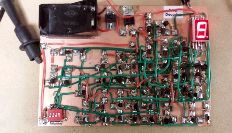
The build began with a piece of copper clad board, a bunch of cheap FETs from fleabay, and an incorrect schematic. While the first version of the project looked fantastic with Manhattan-style construction, and jumper wires everywhere, the schematic was fundamentally flawed and [spencer] got a little confused when converting the circuit to a common anode display.
Version two used a more standardized construction. This circuit was plotted in DipTrace, and the resulting PCB was sent off to OSHPark. The build was cleaner, but in capturing the schematic, [spencer] reversed the footprint of the seven segment display. That was easy enough to fix with a few short wires, and after a little bit of work [spencer] had a device that would convert binary to a seven segment display.


What an incredible waste of time…
You’re welcome.
No. What an incredible learning experience. In preserving and restoring old gear, there are times one must really understand the IC’s involved and, sometimes, work around the unavailability of a device. If you are of the type that feels preservation and restoration is a waste of time, then you are, IMHO, an empty shell.
Yeah, we don’t need articles about people building stuff. Better to spend our time on moon landing conspiracies and articles about how Stallman was wrong. /s
So what you’re saying is… At least it’s a hack!?
OK. I wouldn’t mind seeing more like this. Some projects are more profitable than others though.
https://gist.github.com/numinit/f02f22a644a69fce1f1e/raw/remove-hackaday-comments.user.js
Can you guys make this a default feature?
Default?
urgh, the link didn’t make it: https://gist.github.com/numinit/f02f22a644a69fce1f1e
honestly, incredibly discouraging threads like these make me want to just skip having the comments there entirely
3000 amps through an iphone a day?
Absolutely… Wire wrap is much quicker when prototyping.
Especially if you have a wire wrap gun. (or a biro)
If every thing in life had to have a point the world would be a very boring place. Why fly RC planes? They don’t serve a purpose. Heck whats the point of art or having a home theater set up. They don’t serve a useful function.
My point being were not Vulcan’s. Some times it’s the journey of discovery that’s fun and not all entertainment has to be useful.
Sounds like you’re strong enough to handle the naysayers but even so…
to everyone who criticizes people like Spencer for wasting time/money on ‘lame’ projects, go f*** yourself, doubly so if you’ve never built anything. This is how a lifelong love for designing and building gets started.
My fav comment so far.
your project is incredible man one of my dream projects is to make a mainframe computer built from transistors diodes and resistors building up component boards to assemble into daughter boards to fill a cabinet
and be able to theoretically assemble the end product with salvaged components from old hardware
im a little jealous of your time to do something i really want to mess around with but its nice to get a glimpse at it
keep on being awesome and make more of this stuff its tits. hell man make a V3 of this project that has the DIP16 form factor on the bottom and use it as a plug and play replacement i would love to see that
You’re an incredible waste of air.
You’re an incredible waste of oxygen.
Not worth the electrons it took to store it.
your face is an incredible waste of time ;)
Seriously though. It’s a hack. This is hackday. ‘nuf said.
Im hopping on the f*ck-you-train here. Cool hack and great learning experience. You are clearly on the wrong website if you dont appreciate those things
Not as much as your comment.
Why comment on such an old article?
Kudos to him! He’s built something and along the way learned more because of his mistakes than someone who built it perfectly the first time ever will. Every time you build something right the first time, you develop a blind spot that will cause you to overlook a problem because “I built it once, and it worked, so it can’t possibly be that section where the problem is”..
Digital not digitial.
You write the article next time.
You are hiring again? :)
Fun little project. What I would have learned from the picture? Using only one or two wire colors to make such a design is a pretty safe way to mess up somewhere and have a hard time finding the errors. Something we already learned back in the last century where making wire harnesses wrapped in wax cord and using wirewrap for circuit prototypes was still in my daily business…
You are correct about the wire colors. In retrospect that was a huge mistake. All I had on hand at the time were those three colors and I was a weee bit impatient. If I try similar projects again I think I’ll stick with SMD.
Back in the old days, you could also use a 2716 EPROM to decode the segments – since they were cheap and could be strobed for multiple parts, you just figured out the pattern, burned the data value in the first 16 addresses, and could use the data out lines to control the segment on/off and using the address lines to control what to display using the first 4 bits (hex display output if you wanted). Another waste of time, but an interesting use of non-volatile memory.
Cheap? I seriously doubt that a 24 pin ceramic chip with a quartz glass window have ever been cheaper than a dedicated small standard chip like 4511 or one of its TTL brethren. But agree to the part of “interesting use of non-volatile memory.”
Depending on circumstances, cheap. When they started going out of style, they were available as new and used surplus by the pound in some places. I was fortunate to live near Cambridge back in the 80’s, and there were a number of sources there, and I would bet other markets had theirs, as well (the Bay area, etc) I probably still have a bunch. I know I have a few hundred or thousand metal-on-ceramic 16 pin DIP fusable jumpers I got in a grab bag sometime around ’85.
Why did he try to hide his name on the version 2 PCB? We know where he lives but he doesn’t want us to know his name?
At the time I thought I would release this anonymously but I changed my mind.
Are the small pcb squares he used to build the prototype the mesquares sold at qrpme.com or something else?
I ask because I could not find anything like them (and the excellent mepads too) sold in EU and shipping from the US is slow and pricey.
Yep that’s exactly what they are. I could make my own but they have a cool style. Sorry to hear about the shipping. On the bright side they last a while.
Out. Standing. Unfortunate about the footprint error, but at least he fixed it!
I’ve always suspected that the schematics published on datasheets had deliberate errors to discourage cloning. Put enough correct circuitry to help understand how it works, but deep down in the guts, some kind of nonsense to make it useless.
I like the Manhattan version, myself. Having built a number (greater than zero) of digital projects using deadbug techniques, but noticing how hard it is to mount discrete components that way, I’ve been itching to try something like Manhattan construction. There’s a variation on Manhattan whose name I can’t remember now – something related to some English or Scottish city, or someplace in New England – but the difference is that you just etch a bunch of square pads in a grid pattern and use them a little like a cross between perfboard and Manhattan. There was a recent article here on HAD that used this. Now that I’ve seen the RIGHT way to do toner transfer (http://hackaday.com/2016/01/12/even-easier-toner-transfer-pcbs/), I just might give that a try. And then there’s the method somebody somewhere suggested (I think this was in an old book?), where you start with a piece of bare copper-clad board, and solder one lead of 10 megohm (or higher) resistors to it to use as standoffs. Bought in bulk, they’re very cheap, and most circuits will work just fine with 10 megohm resistors to ground all over the place.
Any other clever and easy tricks out there for hacking a circuit together on a rainy day?