What would you get it you mashed up an FPGA and an Arduino? An FPGA development board with far too few output pins? Or a board in the form-factor of Arduino that’s impossible to program?
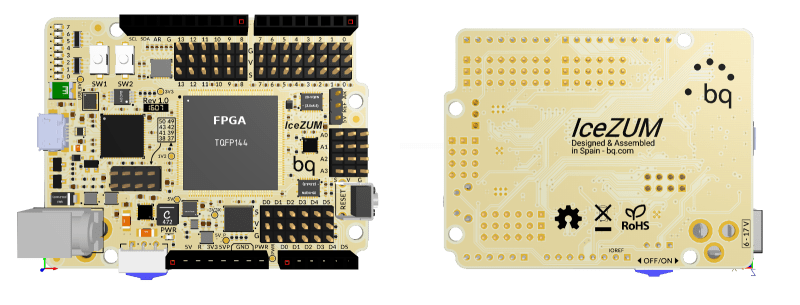
Fortunately, the ICEZUM Alhambra looks like it’s avoided these pitfalls, at least for the most part. It’s based on the Lattice iCE40 FPGA, which we’ve covered previously a number of times because of its cheap development boards and open-source development flow. Indeed, we were wondering what the BQ folks were up to when they were working on an easy-to-use GUI for the FPGA family. Now we know — it’s the support software for an FPGA “Arduino”.
The Alhambra board itself looks to be Arduino-compatible, with the horrible gap between the rows on the left-hand-side and all, so it will work with your existing shields. But they’ve also doubled them with pinheaders in a more hacker-friendly layout: SVG — signal, voltage, ground. This is great for attaching small, powered sensors using a three-wire cable like the one that you use for servos. (Hackaday.io has two Arduino clones using SVG pinouts: in SMT and DIP formats.)
The iCE40 FPGA has 144 pins, so you’re probably asking yourself where they all end up, and frankly, so are we. There are eight user LEDs on the board, plus the 28 I/O pins that end in pinheaders. That leaves around a hundred potential I/Os unaccounted-for. One of the main attractions of FPGAs in our book is the tremendous availability of fast I/Os. Still, it’s more I/O than you get on a plain-vanilla Arduino, so we’re not complaining too loudly. Sometimes simplicity is a virtue. Everything’s up on GitHub, but not yet ported to KiCad, so you can tweak the hardware if you’ve got a copy of Altium.
We’ve been seeing FPGA projects popping up all over, and with the open-source toolchains making them more accessible, we wonder if they will get mainstreamed; the lure of reconfigurable hardware is just so strong. Putting an FPGA into an Arduino-compatible form-factor and backing it with an open GUI is an interesting idea. This project is clearly in its very early stages, but we can’t wait to see how it shakes out. If anyone gets their hands on these boards, let us know, OK?
Thanks [RS] for the tip!


just No. I like my arduinos, but FPGAs should have a nice board with IO nicely accessable. You dont just trow in a fpga like this. It just feels wrong. Only if the IDE is as simple as the arduino one… then maybe…
The GUI that we linked in the article is nicer/easier than Arduino in an FPGA-sort-of-way. Are we there yet?
Well it’s still all sort of out of balance. I think a PSoC wold be a much better choice for beginners as long as it had a IDE that is as simple and easy to use as the Arduino IDE. Some of the new Cypress PSoCs are great but the software isn’t the best for beginners. In any case it’s still far simpler than a full FPGA design environment.
What we have here (by the looks of it) is a dense FPGA and a schematic entry IDE. If you were to use up most of the FPGA with a design then the printed schematics would cover a couple of football fields. Nobody can keep all that in their head when they’re designing and that’s why we have Verilog / VHDL.
The “make” or “break” of this is going to be how easy it is to use the IDE for slightly more complex designs.
It’s like putting a V8 engine on a skate board – you just know it isn’t right an something has to give.
Well from their web site –
Available in three series with LUTs ranging from 384 to 7680
Much smaller than I expected for a QFP144. Really … if you don’t need the number of pins then you would choose a smaller package unless you needed more LUTs. Maybe QFP144 *is* the smallest package.
So not as bad as I suggested but still too big for any reasonable schematic entry.
Then it has Verilog which doesn’t make sense again. Most people that have enough experience to use schematics normally prefer VHDL as the two are closer together. Verilog is more abstracted away from hardware and that isn’t a problem if you were never into the hardware anyway. BUT … If you were never into the hardware then you probably know nothing about schematic entry. Makes no sense to me.
I think that the reason that there is so much use of Verilog in Merica is that all the old IP was written in Verilog. It only has a strong hold in Merica as far as I know. The rest of the worlds seems to be using VHDL (exclusively). Mericans tend to use both. I dunno why ??? Do you design in VHDL then convert to Verilog for ASIC production?
Anyway – choosing Verilog makes your product and American Domestic product and not an international product. And that makes me wonder why I even see it on HaD which is a global website??
I for one won’t be putting any effort into learning Verilog just to suite Mericans.
I spose it’s like Metric ‘vs’ Imperial. The people that invented Imperial – now use metric. But not Mericans!!! no they still use imperial lol.
1000 years from now –
“I’d like 1000 gold-pressed Latinum in one foot lengths”
“Ah so your American”
“How can you tell?”
Like it or not, a huge part of the worlds machining capacity is in the US, as well as all of the standard materials etc. that go along with it. When I talk to experienced machinists here (the US) they roll there eyes about changing to metric completely, as they can never get away from all of the existing stuff, and companies that use it. It is much easier for them to use imperial unit based CNC machines, and convert to metric than vise versa. If your little snooty european “country” is as big as one of our states, then sure, switching everything over is no big deal.
I hear what you are saying about the “problems” but realistically the rest of the world solved all these “problems” a long, long time ago.
We went metric in 1972.
And apart from guns / weapons, America doesn’t actually export much that has been machined. It’s mostly domestic products because the rest of the world isn’t interested in stuff made to imperial specifications.
And I suppose America is a big place if you live there. Don’t look at China or Russia lol.
The per capita machining capacity of America isn’t greatly different to most western countries, we all caught up long ago.
And here is a pic of my “snooty country” –
http://s-media-cache-ak0.pinimg.com/736x/95/57/49/9557493aeca2e4a9f898812d0f4e3804.jpg
Sparkfun sells a PSoC dev board with a lot of features:
https://www.sparkfun.com/products/13229
It is a touch expensive, but then again, a genuine Arduino Zero is damn expensive too.
There is a bitstream that makes it act exactly like an Arudino, insofar as using it with the Arduino IDE. It is also kind of great that they provide a template for use in the Cypress IDE that acts just like a sketch, with main() and loop(), and links against the whole ported Arduino library.
Cypress definitely does a lot of things right. Their IDE is free free free, without even a login to download it. Their IDE has a complete arm-gcc-non-eabi toolchain in it, which runs on Windows, so no piecing together eclipse and plugins and toolchain downloads. They have a number of *great* and very educational videos on YouTube featuring a plucky young applications engineer, walking people through some PsoC tutorials. They sell some wonderfully cheap little “dev sticks”, which have a WORKING DEBUGGER on them:
http://www.cypress.com/documentation/development-kitsboards/cy8ckit-059-psoc-5lp-prototyping-kit-onboard-programmer-and
(if someone just make a breakout board that adapter that stick to Arduino form factor, plus the usual power stage, you could probably make money right selling it right now)
They also get some things wrong, though. Their website looks and functions like something from 2002. It is hard to wade through all their products to find downloads and datasheets. And as much as I extol how great their IDE is, it could use a few tweaks to make it better. (I think it is based on VStudio, which is a great IDE platform, but this is some junior version of it)
Does anyone know anyone at Cypress? Seriously, they need to get their shit together over their USBART drivers. The tutorial for the FreeSoC2 board say that you have to disable driver signing to use the driver they provide (generated by the IDE), but it turns out that there actually is a signed Windows driver. Unfortunately, it is not on whatever server MS does automatic driver downloads from, and even when you do have the right driver to install, you have to do the esoteric “Have Disk” method to force it to use the driver.
A big part of the success of the Arduino is that it just works when you plug it in … missing that functionality is just so hobbling.
Maybe I should just go down to the Cypress office in Santa Clara and ask to talk to an apps engineer or someone on the Windows driver team?
I agree about Cypress and there software.
I downloaded the creator studio or whatever it was called from their website and I couldn’t get it to play nicely. I was installing it to Windows XP which is very dated now. The download package (ISO) included a previous version of creator and when creator was updated after the whole package was installed the hole thing fell to bits lol. I tried to fix it and I am an experienced computer maintenance engineer.
Now (some 6 months later) I haven’t gotten back to this problem. After the trouble I had, Cypress updated the software package (ISO) on their web site so in theory I just need to start over.
But … I have this to say about Cypress. They were extremely helpful. The technical support was excellent right through to the extent that updated their web site to support what really is an outdated operating system. M$ doesn’t even support XP anymore.
So – yes – definitely contact Cypress about the driver issue. You may find the experience to be a refreshing change from the level of technical support that we *don’t* get from Xilinx and to a lesser degree Altera.
I have a bunch of FPGA and CPLD boards. Truth is I like being able to buy a shield from a Chinese ebay seller for £1.50 and just plug it in.
FPGAs should have I/O exposed but the arduino layout is handy.
Remember these are experimentation and dev boards.
I mean, kinda. I think this would be a great teaching tool, as most FPGA devboards have way more bits on them than a class will ever use. Hell, you’re lucky to get more than 10 pins out of a class. And, y’know, if I’m just poking at something to try it out with an FPGA or trying to get a chip to work with one I can see this being very useful.
AbstractionNightmare.begin();
ROFL – we hear you ‘o’ wise one!
There already is a great Arduino FPGA board made by Justin Rajewski
https://embeddedmicro.com/products/mojo-v3.html
There is an active community, and you can either use the full IDE or their own custom tools. It worked great for me when I needed to do some high speed IO synchronization without an expensive dev board.
If they figure out a way to make FPGAs easily programmable, it’s gonna be gold.
Maybe something GUI-based, with lots of colorful boxes to put here and there?
For the board Papilio Duo there is a GUI-based interface looking like the Arduino One that allow to configure the FPGA using Drag&Drop of components schematics
here is an example
Can you post a link?
I know they have an Arduino IDE but I thought that only worked with a soft processor so that it’s just like programming an Arduino – not FPGA.
I RÖB I`m sorry but my comments containing links are not published :-(
Just search for Papilio DesignLab and you will find some videos explaining how the tool work.
They extended the Arduino IDE to add an FPGA specific part allowing user to manage both FPGA and AVR with the same soft. The tool is open source and it doesnt prevent you to use Xilinx IDE if you want to manage FPGA part by yourself
OK, I found it on youtube and it is just using the schematic editor of the Xilinx ISE.
That really isn’t making things any easier for beginners! ISE is a pain to use and has a steep learning curve.
There are GUI tools, but in all honesty if you don’t use the nitty gritty verilog how on earth are you going to create a custom interface?
Well that’s more or less what they have done so it sounds like it might suite you.
The problem is where the limits lie. One cleverly written page of VHDL could be represented with reams of schematics.
The usefulness of schematic entry expires due to the potential complexity that the hardware can host.
You can spend months designing 400 pages of schematics, then what do you want to do with the other 99.999% of the FPGA chip. Put simply schematic cannot scale to the size of modern FPGA chips.
nothing special ! http://lcamtuf.coredump.cx/edison_fuzz/edison-cluster.jpg :)
Eh? You realise that an Edison is an x86 based microcontroller, so effectively just a faster Arduino, whereas an FPGA allows you to define custom interfaces (so you could, for example, offload WS2812 protocols to hardware). Not the same thing at all.
Does the world need arduino stops using that stupid pinout?
https://xkcd.com/927/
That footprint makes sense for a little CPLD (XC9572 etc), but if they’re going to do that to a non-trivial FPGA, it at least needs to use the Mega layout and have a couple of 2×20 IDC connectors on the end to mop up the leftovers.
My thoughts exactly.
The Arduino I/O pinout might be fine for really low speed signals. For high speed signals (both clock frequency and edge rates) coming out of a FPGA, I would expect a lot more ground signals for better signal integrity.
That’s one of the reason why I actively avoid any Arduino form factor products as they are limited in I/O bandwidth both in pin counts and speed.
It loiks very close to the Papiluo duo board I biught nearly one year ago
And the FleaFPGA Uno board I bought a few months ago…minus the HDMI, USB host, composite out AND ESP8266.
Also minus external RAM and a more capable FPGA :-)
Still, this is a cool open-source board. They may want to consider using a larger HX4K ice40 imho.
Cost?
The main reason I didn’t just “buy now, figure out a use later” an FPGA board is the cost, even the cheapest ones go for $50…
The cheapest I know is 37.99$…
You’re not trying. A quick perusal of EBay shows CycloneII boards can be had for about $15, or $18 if you throw in a USB Blaster programmer with it. Rather more complete CycloneV based boards (with VGA, SDRAM etc) are $40.
Cypress semiconducters sells the cy8ckit-049-42xx for $10.
Has four ports + you get a second chip as part of the kit with a few pins on it + the serial goodness
The 42xx 43xx are good but …
http://www.cypress.com/documentation/development-kitsboards/cy8ckit-059-psoc-5lp-prototyping-kit-onboard-programmer-and
This board is a better buy. It has full debugger and the snap off interface is a full JTAG interface and not just a serial bridge as is the case for 42xx 43xx.
Cheapest I know, AND use, is the £4.90 cheap Chinese boards.
Which one? I would like to start with fpga, but I don’t want to spend much more money then on a lunch :)
Here are a few I found on ebay, all from china. The FPGA is a cyclone II so if you use Quartus II you will need 13.0sp1, for the CPLD I think the latest one (15) works fine, personally I don’t use it as I have a DE1 (cyclone II based).
You’ll need a bus blaster to program the device they are cheap too about £3.
Looks like the FPGA was more pricey than I thought but the CPLD is still only £4.90, as far as most should care CPLDs and FPGAs are identical if a bit smaller and less complex. You use the same software to design, flash and simulate them, in the same languages. And you will easily find a softcore to fit into a Max II, bet you probably don’t want a softcore so much as versatile glue logic which the CPLD is great for.
The Max series although sold as CPLDs are architecturally FPGAs (i believe).
FPGA £10.90 ono
http://www.ebay.co.uk/itm/1PCS-ALTERA-FPGA-Cyslonell-EP2C5T144-Minimum-System-Learning-Development-Board-/191770242510?hash=item2ca665adce:g:XhwAAOSwNyFWgymW
CPLD £4.91
http://www.ebay.co.uk/itm/Altera-MAX-II-EPM240-CPLD-Development-Board-Experiment-Board-Learning-Breadboard-/121362597097?hash=item1c41c644e9:g:QnwAAOSws65TmRjw
And you will need one USB bus blaster (altera jtag interface clone) £2.60
http://www.ebay.co.uk/itm/Altera-Mini-Usb-Blaster-Cable-For-CPLD-FPGA-NIOS-JTAG-Altera-Programmer-/272097471982?hash=item3f5a45edee:g:zrwAAOSwT5tWPcna
I posted a long reply about it but looks like the spam filter caught it due to the ebay links.
TL;DR Max II EPM240 dev boards form chineese ebay costs £4.91 they are really FPGAs (the distinction is mostly due to size and complexity when it comes to Altera the latest Max devices are amazing. MAx 10 I think). There are also cyclone II dev boards for about £11 these need you to use Quartus Web II 13.0sp1 as they are not supported in the latest versions. you also will need a programming interface usb bus blaster clones cost £2.60
EPM240 is Altera CPLD (not FPGA) but in my opinion its a better chose for a learner. The differences between FPGA and CPLD is that CPLD are much smaller (less complex) devices and they stay programmed when powered off. FPGA have to reload their “configuration” from a memory chip when they power up.
Also FPGA is 1.8Volt or 2.5Volt or 3.3Volt and can’t work with 5 Volt chips.
The CPLD chip mentioned (EPM240) has a 3.3 Volt core and is “5 Volt tolerant” so it can work with 5 Volt chips. There is also a EPM570 which is the same but with more logic inside. Altera programmers are also cheap $25
They also have 5 Volt tolerant CPLD like XC9536XL / XC9572XL. They are much simpler then their Altera counterparts but are easier to solder QFP44 0.8mm – The altera CPLDs mentioned are QFP64 0.5mm or QFP100 0.5mm
EPM240 about 200 logic units / registers
EPM570 about 500
XC9536XL 36 logic units / registers
XC9572XL 72 ….
Altera programmers are also cheap $25
Should read “Altera programmers are also cheap < $5"
Architecturally they are far closer to FPGAs than CPLDs. Really altera sell them as CPLDs because of their modest features.
https://www.altera.com/products/cpld/max-series/max-ii/overview.html
HaD lost my longer post some theres a bit missing in translation in the smaller one. I know they are sold as CPLD but the difference from an FPGA is really trivial in the Max product line.
I second Petr’s question. Any links? I too would like to get into FPGAs, but my budget is really small. I’d love a cheap FPGA with tutorials or something to help me get started.
See above.
Basically eBay epm24 dev board. Ignore the fact that its a CPLD for now. In actually its a low end FPGA
cy8ckit-049-42xx
$10 from Cypress semicoductor, I have two.
$2.92 US (including shipping) For a small Coolrunner II board. Only six IO lines are brought out, but it is a cheap way to get started. The connections are- A=P20, B=P7, C=P45, D=P32, E=P33, F=P36. There is a 48MHz oscillator on board connected to P45 that can be disconnected if not needed. The board (and CPLD) is a 3.3V only design. But you can also set it up for 1.8V logic. It is not 5V tolerant.
http://www.aliexpress.com/item/XILINX-CoolRunner-II-FPGA-CPLD-XC2C64A-Core-Module-Mini-DEV-Development-For-XBOX360/1878839883.html
These boards are so low cost I have been hot-airing the CPLD’s off and putting them on my own breakout board design. I would be happy to share the Gerber for the board if anyone is interested.
Xilinx ISE Webpack is free (but it is a huge file), from the Xilinx website.
For a programmer I use an old laptop with a parallel port, and I built my own Xilinx JTAG parallel port programmer. –
https://www.sparkfun.com/datasheets/DevTools/FPGA/fpga_prog.pdf
But you can also just buy one for less than $4.50 (including shipping) on AliExpress.
An excellent starter info source is –
http://dangerousprototypes.com/docs/CPLD:_Complex_programmable_logic_devices#CPLD_development_tutorials
Would have been great to have a similar design but with an additional SRAM chip. ice40 1k is too small.
The Papilio Duo board I bought has 64bytes of FPGA Block Ram + 2MB SRAM.
The Arduino core also has its own memory. This is a very nice board
*64KBytes of Block RAM :-)
*64kBytes of Block RAM :-)
SI is k
Nobody would have assumed I meant Kelvin in the above context.
And by extension – nobody would have believed the 64 Bytes either lol – all good :-)
“all good :-)” Good for you..
No one will ever need more than 64 bytes of block ram
Deep deep belly laugh :-)
Check this out if you want a nice FPGA for a reasonable price:
cypress.com/part/cy8ckit-049-42xx
You score a USB-Serial converter in the process.
That’s not an FPGA. The Cypress UDBs can be very handy but the fabric is very tiny in the 4200, it reminds me of an old gal20v8. You can use Verilog to define the logic so that’s a plus. I prefer the PSoC 5LP even though it’s a few dollars more.
I still have a stick of (20 odd) 22V10’s in a J package here. I don’t know what I can use to program them and I think they’re OTP anyway.
You compile a JEDEC file from a set of logic equations or a truth table. I have a TL866 I use for programming eeproms and pics but it also can do PALs and GALs. Once you compile the logic into a .jed you can use that file to program the chip. GALs are reprogammable, PALs are OTP.
Here’s a few references
http://www.uchobby.com/index.php/2008/03/30/gals-for-electronics-hobby/
https://github.com/daveho/GALasm
Use OPAL Jr or if Lattice, ispLever Classic
An “FPGA Arduino” implies it can run sketches. 1K device is too small to put an AVR8 core inside. So it’s just an compatible board. But no worries, an “FPGA Arduino” with enough gate capacity for an AVR8 core has been done before:
https://www.youtube.com/watch?v=_xDBaDeZpa8
While it’s built as a shield, the included DC power input along with female IDCs in-place of the bi-directionals would make a nice base-board.
Why oh why would anyone want to run arduino sketches on an fpga? AVR hard cores cost peanuts…
Much better to tie one to an FPGA and use it for fancy glue logic.
Why? Because the platform is extensible. If I want to offload superfast PWM, QSPI, or some other digital functionality I don’t have to change the hardware. I sometimes use FPGA boards to emulate hard microcontrollers to cut down on development and debugging time. Putting extra logic in a Verilog file and clicking rebuild is much quicker and less error prone than wiring up a bunch of logic on a breadboard. I think that’s why FPGAs were invented.
There is always the Atlas-Soc board from Terasic
http://www.terasic.com.tw/cgi-bin/page/archive.pl?Language=English&CategoryNo=205&No=941
I think you’d be better off with a snicker doodle board instead http://krtkl.com/
I’m still waiting for mine! That board is going to be absolutely made or broken by how good their software and ecosystem support is. Not that many people are going to want to download the whole Xilinx ISE WebPack Vivado HLS whatever-the-hell they call it now, and do hardcore verilog. A few people in the community will do that, and then provide good bitstreams to everyone else, like how Adafruit stewards so many of the Arduino libraries.
Just what every Arduino user needs:
– hardware support for FastLED library.
– flexible shift register driver
– auto LED blinking.
– auto button debounce with READY flags.
– etc, etc
Just go through the forum and get more ideas.
This could eliminate even more thought and involvement in electronics and programming!
I once bought a really bad counterfeit Arduino off of EBay. It was actually just an board with Arduino header sockets and a 555 connected to pin 13. The scary thing was.. the guy selling it had mostly positive feedback!
https://xkcd.com/325/
For the love of god, why did you not take a picture and make a whole HaD post about that?
Arduino has a crappy pinout, with (among other things) too few grounds, “toy” connectors, and weird pin spacing. The mounting holes are an afterthought (they readily double as short circuits). The board outline is needlessly irregular. The board-to-board spacing short circuits for many common connectors (i.e. USB-B, Ethernet). The marginal power supply section has been revised based on user comments and reflects the “designed by committee” result that you would expect.
So why would you want to copy this format?
Unfortunately the irregular shape and the afterthought mounting holes are the norm now. Actually.. they are not… no mounting holes at all is more the norm now. These days we have more inexpensive circuits available to the hobbyist than any other time in history. But.. they are smaller and smaller SMDs making PCBs very necessary. Those PCBs are getting designed by/for people who never actually permanently mount anything inside a box. They just lay it out on a table with temporary jumpers and take it all apart again when they are done. I guess those extra mm^2 of PCB material that would be required to make things usable for the few of us who actually do want to make permanent devices is too expensive when multiplied by units sold.
Arduidiotino is for people who want to program _without_ learning how to program. FPGA wont work for those people.
FPGA development boards with an arduino form factor…
FPGA’s excel in speed and flexibility at the cost of being generally more difficult to program.
Now you could argue that the only reason that FPGA’s are difficult to program is because Verilog and VHDL are horrible languages but you cannot convince me that having several clock domains, multiple lines of code which execute in parallel and implementing a state machine so you can communicate with your arduino shield through I2C / UART / SPI is by any means feasible for your typical ‘arduino’ enthusiast regardless of language and abstraction.
But lets say you are ready for the next step; why bother using arduino shields anymore? The shields are specifically made to run on an arduino, will do so with minimal code because of the huge collection of libraries, don’t typically profit from parallel processing power and would take time and effort to implement on an FPGA with little to no added bonus.
“But if someone writes module X that would allow me to use shield Y without difficulty”. If you are unable to write code to control a shield, believe me.. you probably won’t be able to write code to use the module in the first place. Besides you need a community of people that are capable enough in VHDL / Verilog to write these modules which seems unlikely to happen because this is a dev board that doesn’t even break out half of its IO and probably won’t attract these people in the first place.
“But using code / shapes people are familiar with will help their transition to X!”
Except when it doesn’t; if something looks like a duck, swims like a duck, and quacks like a duck but isn’t a duck it will confuse the hell out of people.
Familiarity will make people apply the same model to something even if it’s not the same, impeding their progress because they first have to unlearn stuff before they can learn new things. It’s way more error prone, frustrating and takes up more time then just learning to do it the way it was supposed to be done.
So please, if you are really interested in teaching people stuff or are trying to motivate them to use a new platform DON’T wrap it up as some existing popular ‘ware if they are not similar enough otherwise you’re just being counter productive to everyone. So to answer your question Elliot; “No”.
“But lets say you are ready for the next step; why bother using arduino shields anymore?” Because it is hard for baby to let go of Mama’s teat.
Well there is a lot of truth in that. Being comfortable using the Arduino IDE might encourage some to move onto FPGA but it also introduces an extra step because schematic entry won’t scale to modern FPGA so they will still need to learn VHDL or Verilog. But if it helps some all good.
But still I see it as unbalanced …
Want to learn how to lay bricks … sure … orders 17 truck loads of bricks …
Poor learner … “I just want to build a BBQ and now I will have to use all of these brick (that I don’t like) or throw them away”
Don’t know why you can not use schematic entry. Is it because you can not? SO quit bashing something you either, don’t understand yourself or too stuck on your own methods and afraid to learn some other way. You can also draw schematic and comile to either VHDL or Verilog. then use the output as a module later? But you seem to spend all you learning time here bashing what other people do.
No, please, FPGA is IT cheating… Am I the only one that feels this ?
So, who woulda thought that you could have a camera that made phone calls, right? TV that dispenses gasoline? Thing is, if you’re advanced and specialized enough that you want to take on fpga’s, I think you’ve pretty much graduated from the arduinos and pi’s, so where’s the market? Then again, you’ll always have the niche group that insists on building 1/12-scale Millenium Falcons with LEGOs, so it’s good to have a choice, I suppose.
you have to read about: http://maximator-fpga.org/
Hi!
I’d like to inform you all that is avalialble nice and cheap FPGA starter board – MAXimator – based on MAX10 Altera FPGA – in Arduino-comaptible connectors and mechanical layout. It’s complete starte kit with USB Blaster compatilble programmer and shield with 7-segment LED 4x displays, WS2812B LED-RGB, anlog temperaturę sensors etc.
All details:
maximator-fpga.org
Unboxing video:
https://www.youtube.com/watch?v=83PMLBczxNU
Avnet makes an affordable arduino-syle FPGA development board using Microsemi’s Smartfusion2 SoC. It is basically an FPGA with a Micro-controller Subsystem (MSS).
https://products.avnet.com/shop/en/ema/development-kits/3074457345623472926