[nebulous] has a lot of problems with his kitchen cabinets. Aside from a noted lack of micro-controllers, he was especially suspicious of the dark spaces under them. Anything could be hiding there.
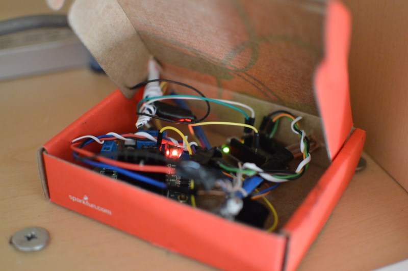
The core of the project is a $10 Arduino-compatible esp8266 board from digistump. The board is powered by the five volt regulator of an L298N motor driver module hooked to a power-supply. All this controls a set-of LED strips adhered to the underside of the cabinets with the traditionally bad adhesive strips with which they come standard. We can predict an hour spent bent awkwardly cursing at them, a hot-glue gun in one hand, in [nebulous]’s future. The whole set-up is housed in a SparkFun cardboard box above the microwave. You can barely tell it’s not a commercial product.
We’re not certain if we like a future where even our cabinetry has an IP address. However, this is a good weekend project that could make all our cabinetry brighter, safer, and more connected.


Flameproof of course, no problems there…
Having a similar problem in my kitchen I took the easy route and just connected the led strip psu to light switch in the cooktop range hood.
I also added segments of LED strip to the under side of each shelf in the pantry connected to a 12V SLA via a micro switch on the door.
I don’t have wifi control or dimming functions – maybe a project for the future
Here is a much less costly solution – less than $30.00!
http://www.instructables.com/id/Under-Kitchen-Cabinet-LED-Strip-Lights-for-Under-3/
You missed the whole point of the project in your haste to link your own.
I don’t think I missed the point of the article, it’s a great article. But not everyone has a spare controller laying around and not everyone wants as much control as this author wants. I posted a link to my article to show that there are low cost alternatives for basic under cabinet lighting.
You should rename that Instructable to “How to kill yourselve for under 30$”. The SMPS has a PE terminal which you *might* want to consider using. Then there is that thing with screw terminals and bare copper braids.
AC mains is no joke.
Gerrit, seriously you can do better than this. Don’t just send any garbage up to HaD; you just cheapen your image.
What’s “jokes,” precious?
“You can barely tell it’s not a commercial product.”
I love it! Don’t stop!
(sarcasm) This is way more impressive than thousands of other projects littering hackaday.io. (/sarcasm)
P.S. – We desperately need to be able to use greater than and less than symbols in the comments. I haven’t bothered to test brackets or html symbols, but the one time I tried the actual characters around the word “sarcasm”, the “tag” was dropped.
Testing brackets: [ ] [sarcasm] ] [
Testing html character codes for gt/lt: <sarcasm>
Excellent. So only html tags are stripped, not html char codes or any orientation of brackets (was afraid maybe invalid BBcode might be stripped or something). :D
Vashta Nerada can be a real problem. Good, meaning overly complicated solution.
I have a similar system. Even down the packaging! The difference is that I am looking at using changes in the WiFi RSSI to detect local (people) movement and I syncronise the time daily with a ntp server so it is off overnight / during the day and active when it’s “needed” morning & evening. A bit of an overkill but it doesn’t cost any extra.
The RSSI people detector side of things isn’t very reliable so far and I really need an outside light sensor or something as some days it’s needed earlier than others. I’m also having issues with the ESP8266 resetting itself about 1-2 times a day & am trying to track that down.
i had a similar problem, and found it easier to just calculate day/night with sunwait on my raspi
http://www.risacher.org/sunwait/
You are probably abusing or overflowing a timer. Try time_t type.
Can someone tell me why an Arduino IS BEING USED AT ALL AND A ESP2688
leds
ldr
resistors
caps
transistors
pot for brightness
Maybe a override Switch
ABOUT 5 – 6 VOLTS
DONE
Arduino is over kill.
OHHHH THE COMPLEXITY
ESP8266, strip of addressable WS2812 LED’s, one voltage regulator for the ESP8266 and a 3A5V wall wart… DONE.
works great and under volting the data line at 3.3v doesnt cause any problems.
I think the devil is in the (mounting and packaging) details
An arduino is NOT being used, but an arduino-like esp board is.
A pots?? And how would you control that wirelessly? you’re missing the pointa
“Cabinets are things and things should have IP addresses.”
I laughed out loud at this part. This hack is a work of art.
(satire is art)
Yah, so should my toilet, right?
Uh yes?
I think it would be rather hard to have a toilet measure its own weight, though. You can’t use the volume of water in the bowl; it’s a floater or a sinker, and the specific gravity of urine can change a lot. You can’t use any sort of force sensor, because it’s effectively sitting on a block of wax (and bolted to the floor).
It’s a tricky problem.
An IP address is fine and all, but what if it’s #2? You’d also have to assign an IPU address.
For the record I’ve already been through an hour of bad words and a hot glue gun. Which also sucked. Ended up using a christmas light staple gun to secure them.
I got some double sided foam tape from 3m.
It’s got plenty of sticking power.
there were a few places where I needed to put in wires to accommodate non-90 degree angles… those got plastic wire staples…
@nebulous
I feel your pain. Many are the problems that have made me desire to liberally apply a staplegun. In my case, though, few are the problems that would actually be *solved* by a staplegun.
\[ \alpha \beta \gamma n^{4} ]\
$ \alpha $
The flickering might be because a motor driver is being used to drive LEDs. While a motor has substantial inductance that limits current inrush, LEDs don’t. You need to add an inductor in series with the driver output, and probably need to increase the PWM frequency. Motors usually are driven at 10s of kHz, LEDs are driven at 100s of kHz or more (so that only a small inductor is required).
Interesting. If that were the case however, shouldn’t I expect the strips to always flicker? In my case I only notice flickering during the fade-in sequence.