Servos are extremely versatile actuators used in a large number of applications which need controlled mechanical movement. The usual way of driving them is by using a PWM output from a micro-controller. But if you’re building a robot or a drone which requires a large number of servos, then it makes sense to add smarts directly to the servo.
[Alvaro Ferrán Cifuentes] did just that by building IntelliServo – an add on board which makes regular servos smart by giving them enhanced capabilities as found in high-end versions. His approach is different compared to other takes on this theme. The IntelliServo is designed to replace the electronics in any regular servo and is not limited to any particular make or type. Once upgraded, it’s possible to read the servos position, temperature and current consumption. This allows interesting uses, such as controlling one servo by moving another one, or detecting collision or stalling by monitoring the servo current. Multiple servos can be daisy-chained and controlled over I²C from a micro-controller, or over USB directly from a computer. Each board features an LPC11U24 32-bit Cortex-M0 micro-controller, a DRV8837 motor driver, a TMP36 temperature sensor and a PCA9508 I²C repeater.
The project is open source and the Github repository contains the board design, Arduino library and examples, servo firmware and mechanical parts as well as use instructions. It’s a modular design which allows using either an external controller or running it directly via the on-board micro-USB socket. Check out the videos after the break to see the IntelliServo in action.


Reminds me of the OpenServo. Not bad
Thanks! :)
Me likey as well – any plans for production?
A good, mostly complete solution. Congrats on the nice work!
+1 on the plans for production. I know quite a few guys who would grab these up.
You may also want to consider an alternate version that can handle much more current, or possibly holes for optional extra components in the driver section to beef it up?
this is pretty great
they should probably take a look at http://hackaday.com/2016/02/23/anti-cogging-algorithm-brings-out-the-best-in-your-hobby-brushless-motors/
doh never mind, servos use brushed motors
Not all of them (:
It should allow “torque mode”, where apart from position you send it either what torque or current it should use. The PI(D?) regulator should run on the servo micro itself, so the master controller can focus on things like calculating what force the servos should use, instead of running a bazzillion of PID regulators. One use for this would be more life-llike 6+n-pods…
The torque mode isn’t implemented, it only reads the current consumption at the moment but it would be a great feature.
The PID regulator is indeed implemented on the servo, so the master only has to read/write data when needed and can concentrate on higher-level tasks :)
The torque mode isn’t implemented, it only reads the current consumption at the moment but it would be a great feature.
The PID regulator is indeed implemented on the servo, so the master only has to read/write data when needed and can concentrate on higher-level tasks :)
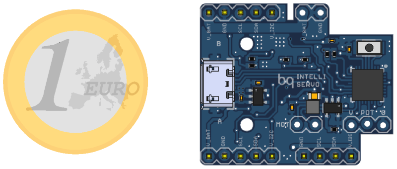
I do not know the diameter of a 1 euro coin. Please change the picture to a US Quarter. Thank you.
” Please change the picture to a US Quarter.”
it’s a good opportunity for you to enlarge your horizon…
It’s roughly two thirds the length of the standard IntelliServo board :)
Its 2.325 cm
0.915354331 Inch, or 58,5 64th of an Inch. About the same size as a Bitcoin.
You mean a 1/4 Freedom Token, right? I’d quite like to see it scaled against a three halfpence coin, but I’m old-hat like that.
/s
As much as I’m sure this is flame bait, one can always scale from the micro USB port, no? That gives a far more accurate sense of scale to anyone familiar with hardware ; o)
Or the 2.54mm pin spacing.
Will you metric-lovers ever give up!?!? Trying to force us all to use your metric pin-spacings!
(Get it?)
Troll b*stard
I was wondering if the DRV8837 included current sensing, but it only has current overload protection. For those too lazy to look up the schematic, he’s using a LMC7101AIM5 OpAmp and a small shunt resistor on the DRV8837’s motor ground.
This is very interesting. It may be just what I need to move from the purely electrical to the physical realm.. Thanks for sharing!
I remember cramming an 8 pin micro and an H-bridge into a servo a couple of years back. I used a couple of pins to select set points and let the micro concentrate on talking to the servo to get it to where it needed to go.
Wow! A whole 11U24 $2 (at production quantities) with it’s sadly tiny current drive capabilities to run a servo? It seems like this would be a good place for a $0.50 ATTiny 45. But I bet someone on here can come up with a much cheaper uP than that.
Go on then?
You appear to have been so quick to slate the designers choice of uC, that you missed the words immediately after, namely “DRV8837 motor driver”!
1.8A seems more than adequate for the usage scenario that the board is designed for!
I’m perfectly aware that a motor driver was used, it would have to be. Having designed with the 11u24 for some time I grow frustrated with the measly 4mA source/sink for the average pin, it can’t hardly light an LED without a driver.
I may have misinterpreted the relevance of your comments on the current drive capabilities of the uC in this application then?
Whilst the I/O current drive limitation of this uC may be a fact, forgive me, I don’t see those limitations causing any issues in this (somewhat well thought) out design!
I can see the appeal of using a cheaper uC, however, the 11U24 does offer several nice features, such as the “drag’n’drop” USB MSD bootloader, for firmware upgrades amongst other things. A quick scan of his schematic shows a “PROG” button on PIO.1, so I’m going to hazard a guess that this is supported.
I’m not sure what’s the issue (beside cost) with the uC. The low current capability is irrelevant since it only handles the logic part of the servo, the motor being run from the driver, as Tom said.
As for the cost, the ATtiny45 is cheaper, but is lacking in many important aspects.
Space is at a premium, so the fact that the LPC handles USB directly means one can have a micro-usb socket for ease of programming and direct control from a computer without needing an FTDI chip. The socket actually takes less space than a row of 4 2.54mm pins to which connect an external FTDI, since it occupies one layer instead of both.
The ATtiny45 also only has 6 useable pins, whereas 8 are used in this board (analogTemp, analogCurrent, analogPot, pwmMot1, pwmMot2, sda, scl) as well as rx/tx that would be needed for programming since it doesn’t have usb.
I also wanted to move away from arduino because of its pwm frequency. From their website “The frequency of the PWM signal on most pins is approximately 490 Hz. On the Uno and similar boards, pins 5 and 6 have a frequency of approximately 980 Hz”. A quick google search shows the best range for motor pwm is the low-kHz range, from around 10-30kHz. While it is possible to boost the frequencies up to 31250Hz and 62500 Hz respectively, “disrupts the normal operation of many functions that rely on time”.
To avoid this but still keep the project accessible I switched to Mbed for its user-friendliness similar to arduino.
:)
the ATTiny 45 is totally no option to be a replacement for 11u24. it has just not enough pins to control all futures (pins) that is used with the 11u24.
I have been looking for something like this for a while. I checked out OpenServo but it seems to be a dead project. PWM is a throwback to the past and modern digital servos are way too expensive for many of my applications. I would certainly like torque control as I have applications that would normally use limit switches which are a pain to physically incorporate into the setup. A combination of software defined travel limits with software managed torque control (not just overload protection) would make physical limit switches unnecessary.
Nice effort, congrats!. You really should consider marketing this product!
Very nice!
Had to work with some (expensive) dynamixels on my college thesis, and they did disappoint me a bit in documentation and features. But they do sell like hotcakes to colleges and schools … and thus it creates a weird ecosystem where everyone uses them but no one understand how to use them.
Hope you continue working on this, it’s certainly promising :)
Really like the “touch detection” application example. That’s awesome.
How hard would it be to convert the binary touch-no-touch into an approximate measure of torque? If you have current sensing on the motor, you’d be a calibration-step away, no?
Feedback on how much force it takes to get the servo into position could be very useful in the joint of a robot. (Understatement?)
Thanks!
In the video the led simply lights on when the current read rises over a threshold, but it actually reads analog values, so yes, you’d only have to calibrate it.
The main advantage of this project, being a universal board is also its biggest drawback, since each different servo has its own set of PID constants, its own angle range and its own current-torque ratio. So while torque is definitely useful, being so tightly coupled to current I decided to simply use the current for approximate force measurements without having to calibrate it :)