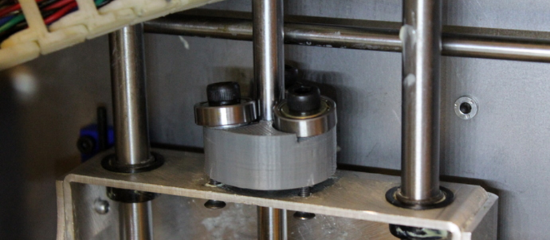
[2n2r5] posted up a mechanism that we’d never seen before — a threadless ballscrew that turns rotational into linear motion with no backlash. It works by pressing the edge of three bearings fairly hard up against a smooth rod, at an angle. The bearings actually squeeze the rod a little bit, making a temporary indentation in the surface that works just like a screw thread would. As the bearings roll on, the rod bounces back to its original shape. Watch it in action in the video below.
The two benefits of these pseudo-threads is that they fit tightly so there’s no backlash, and they give when too much force is applied, rather than jamming. Eliminating backlash is awesome for a 3D printer, but it’s not obvious how a thread that gives under excessive load is a plus, unless you’ve crashed your printhead into the bed of the printer. Generally speaking, 3D printers don’t subject their screw drives to all that much force, making this an interesting option.
A professional version of the same mechanical idea uses special bearings with a ridge in the center, and tips them side to side to change the contact angle, and thus speed of travel (per rotation of the shaft). It’s even got a provision for flipping the bearings over, causing the tram to move in the opposite direction. Pretty cool.
[2n2r5]’s Thingiverse project is from a few years ago, but until we got sent the tip (thanks [Keith O]!), we’d never seen this mechanism before. Have any of you tried it out? Results?


Black magic!!!!
I think this is the best compliment a person can get on a site like this.
Agreed
I’d say “old magic” :P (looks like the reversible design dates from 1952, another spot says 1940’s)
A big disadvantage of a drive like this is that the output position will drift over time. (though periodic homing is likely enough to deal with the drift) Also maximum force is limited compared to a similar size screw or ball screw.
I think this is enough for 3d printing or laser cutting, the tool doesn’t really have a load, only the weight of the cartridge.
probably will not work with machining, since you put a lot of load onto the gantry system.
however this is a whole lot cheaper!
how do you calculate distance per step and all that??!!
wouterlala is right, the guy that made this is clearly a witch. burn them.
Just as usual: Let the slide travel for a known distance and count the steps. You should add some method of anually adding or subtracting one step by pushing a button in order to fine adjust, of course. Then divide (known) distance by (counted) number of steps and you’re done.
Its better to calculate it. Manual measurements tend to give you good calibration prints but overall you get a better print by calculating steps with maths.
That would work for low accuracy requirements – you could just have limit switches at either end and periodically measure the steps (calibrate). It could serve as the drive for a low power laser cutter or something there the load is low and accuracy is not the greatest factor.
It could also be useful for low force movement where there is a human in the feedback loop like an axis in one of those “claw” machines with soft toys.
It is more measuring than calculating.
I am more concerned about the repeatability. How long will the number of steps will remain accurate. Few people like to calibrate every print…
Still cool stuff.
It’s an inclined plane, just wrapped around a cylinder…If you know the diameters of the contacting surfaces and the angle, it’s just trigonometry…
Well, trig, plus physical reality – which is that without hard ways to transfer weight to, the bearing edges will be.. the bearings – and will get worn down. Without inherent method to allow for backlash, they will quickly be useless for precision linear motion.
This is just my first guess.
Well if you do the trigonometry then you will find a number of problems. The first being that one bearing will remain in friction contact while the other two are dragged along.
The second problem is that irregularities in the surface of the actual (ball) bearings and their running surfaces inside have a greatly amplified effect on movement to the extent that they have far greater effect than the outer surface angle of attack and they do so as a result of far minor dimensions.
So you have exceptionally poor repeat ability that will rapidly get worse with the slightest ware. So even with measurement to give initial linear rates you still cant use the rotation of the shaft as a factor in determining linear dimensions.
It’s great for low cost linear “movement” but you need external feedback for any required dimensions.
I think you misunderstood how it works. The three bearings’ axes are at the same angle to the main rod axis, and are tangential to the ‘natural contact distance’ cylinder. Visualize this: put the bearings in contact around the central rod, with their axes parallel to each other and to the rod. Now twist the bearing axes in the plane perpendicular to the center-of-bearing—center-of-rod vector. Because of the symmetry, there’s no slippage—all three bearings roll on the rod. The contact between two off-angle cylinders is a point, so there’s a significant resistance to sideways motion.
On contrary, you are misunderstanding what a bearing is.
What you are calling a bearing is actually the external case. The actual bearings are the balls inside and the mathematical synthesis of their movement is much more complex than the simple movements of the bearing case.
Nothing is ever the “same angle”. It can only be exact to the limits of the resolution you can measure it with. This makes all the difference when you have something that is effectively an culmination error amplifier. And that is exactly what is demonstrated in the video posed in the comments here.
If what you are saying is correct then the accumulated error would be zero and that is absolutely demonstrated NOT to be the case.
Here is my openSCAD version of this. http://www.thingiverse.com/thing:124706
The math is in the file so that you can customize your steps/mm. It is only roughly accurate due tolerances in the printing process but it is a good starting point.
I made an experimental nut and posted on Thingiverse, alone with the way to calculate the “pitch”.
it’s just very basic trigonometric.
http://www.thingiverse.com/thing:1666794
The commercial version would be the Roh’Lix : http://www.zero-max.com/rohlix-linear-actuators-c-24-l-en.html
They are good for when you need low friction rotary to linear motion with little in the way of accuracy. I would not be using them in anything CNC without a secondary source of feedback like a linear scale. Even the commercial ones expect up to .002″ of error per turn.
You see these on things like optical comparators where you just need smooth, low backlash movement and limited thrust.
Good to see you finally got out of the cave Elliot. Easier than committing the act of journalism.
That mechanism has been on Thingiverse for a few years already
How about you read the entire article before acting like a dick ;)
This isnt a ‘news’ site – where did you get the idea everything covered must be ‘brand new’?
He says immediately this was new to them.. New, to them. You can read right?
Maybe you should get out of the basement, attend kindergarten through middle school again, and learn to read, before comiting the act of writing.
Just an idea?
This is an excellent cost down for CNC where accuracy or longevity is not an issue.
But … lol … why is there always a but ?
You loose 25% of your *grip* quality when something slips. and when you have three points of contact then each point has to have enough accuracy (the angle) so that it is equal to the other two point over the full length of the linear (that’s absolutely a high degree of accuracy that is NOT achievable with 3D printed parts) movement and if it is not then you will have slippage so you have to subtract 25% of one third of the linear force straight up.
What is making this “work” to some degree is the fact that the (real) bearings inside the case can slip enough to correct for the difference in travel over the length of the shaft that results from the difference in angle between the three bearings.
Meaning custard custard, bacon, tart, cake, mayonnaise, cow milk! Your subscription has expired.
Here’s a good test of 3d printed threadless ballscrew accuracy (or more likely lack of it):
http://www.thingiverse.com/thing:298212
https://www.youtube.com/watch?v=NA_9GeFxV0o
Perfect! I was watching the whole laser-cutting in the beginning, and thinking “that doesn’t look so bad” then I got to the end.
TD,DW: A test rig moves through representative motions, loses a bunch by the time it gets back home.
This is consistent with all the comments about poor positional accuracy. Thanks for demonstrating it. (Or for finding the right video link.)
This device is only useful in one direction. So you home your printer, then slowly descend while printing.
Moving back and forward simply a no-go.
agreed. This is exactly what I found. Only good for the Z direction and only on printers where the platform moves down. The print quality is amazing though if you use it understanding the limitations.
Nice mechanism! But not suitable for actuators which rely on exactly repeatable positioning. This drive is based on friction alone and while the error along the moving direction may be small, it’s still there and adding up over multiple movements.
There is no way this device has any useful life or expectation of repeat ability and accuracy…the physics simply fail. Its purely clamping force and friction, all of which will yield and/or slip. A ball screw is inclined plane. Nifty parlor trick.
I’m sure there will be slippage and missed steps with this and those bearings won’t last long but it is a nice cost saver!
it remembers me of a helical crayford focuser for telescopes.
like this one: http://www.kineoptics.com/HC-2.html
but there is no repeatability necessary.
It doesn’t look like the bearings are spring loaded to compensate for the mechanical wear on the rod and the bearings. So there are long term issues.
Like others have said, on a system without a position feedback mechanism, the slip will introduce errors. On systems that require force/accelerations, the amount of fiction will be the limit. Not sure how this fits on 3D printing with no feedback and CNC that requires force.
Despite the lack of accuracy, this mechanism still an impressive demonstration of creativity.
Without balls or a screw, it is technically not a “ball screw”. More likely a “bearing rod” linear actuator? Words mean things. This is not only lacks repeatable accuracy and precision, but it could neither quickly accellerate a significant load, nor would it work reliably or safely for a vertical axis. Lubrication would only make it worse, not better. However, it is definately fascinating to watch in operation, and it would indeed have some useful applications (though it would need a position servo feedback mechanism to be useful).
So wouldn’t it technically be a ball rod actuator, since it does use ball bearings? But merriam webster states that one form of screw is a device that turns like a screw, in which case this device would still fit.
Webster is not an engineering manual
… except that traditional ball screws are used where you have very high loads and a reasonable need for accuracy. The design in this article can’t handle any significant loads .
Here is a hybrid approach that uses the same roller bearings, but also uses a screw for repeatable positioning “accuracy”:
https://www.youtube.com/watch?v=P3besV_TDaM
Oh that is so Macgyver! I think some miniature V-track rollers like => https://shop.sdp-si.com/catalog/?cid=p891 would improve wear life and reduce friction, though cost a significantly more.
https://www.youtube.com/watch?v=m6k8Jz_-WCk
Never got to find suitable bearing/rod combo, but the idea seems nice.
Love this.
I see this being really critical w.r.t. bearing angle -> linear encoder ripped from an inkjet printer will be mandatory to get reproducible results. Otherwise the cumulative error will exceed backlash in other systems.
This would probably break down pretty quickly, as bearings are very bad at taking high stress loads on a single point, unevenly distributed. only a matter of time before the ball bearings inside become impinged (or worse, just shatter) and the whole thing grinds to a halt.
But since you have such limits on load due to being a friction fit between bearings and rod, you can simply adjust the “prelaod” to suit the required load on the screw, that should help reduce any wear and breakage/work hardening due to single point contact. It also might be possible using a fine abrasive to lap the bearing surface against another rod of the same diameter to create a concave surface on the ball bearing outer races. This should help spread the load just a little bit more along the surface of the bearings.
I wonder why not use a rubber sleeve around the bearing, to increase contact area and (static) friction for holding force, that does not mean friction on the drive train, that would still be nearly smooth (think bicycle tires)
since still rolling without slipping
Accurate except it would increase friction on the drive train. Which may be an acceptable trade-off in some cases.
Oh, the humble bearing … a some balls and two cups (lol no … not that one)
There are various designs for simple bearings and there is a lot of math that goes into the perfect design for a particular situation.
These common garden variety bearings have a spherical bearing running in two hemispherical tracks.
except that the tracks are NOT perfect hemisphere of the same radius as the ball … because the speed of the ball is different in different positions. It is slowest on the inner bearing, fastest on the outer bearing and graduation of speeds between to the two extremes so if the tracks were the same radius as the outside of the ball then the bearing would simply bind solid because of the different speeds.
So .. the tracks have a larger diameter than the ball. Then ,,, what happens … when you apply force at an angle … the ball makes contact with the track at a slight angle rather being dead center of the track.
This causes the ball to spin on an axis that is not aligned to the bearings feature – surprise surprise much like what is happening on the outer surface.
This spinning motion is much like when you flick-spin a coin on a table – that it – the spinning speed is much higher then the general movement of the coin.
And this motion (that the bearing was not designed for) will cause the ball (and therefore bearing) to wear very rapidly.
Now that’s not the end of the world because there are bearings that are designed to take a ‘thrust’ component of load like tapered roller bearings for instance. These would give the opportunity to align the bearing angle to a mathematical perfection for minimum wear.
That leave the remian points –
When something slips (like you car tires) they loose 75% of their load bearing ability and you are left with only the remaining 25% and that is why cars have anti-lock handling and breaking systems.
If you do the math on how this bearing works then you will see that you have a real live physics engine failure much like when you see a car mostly integrated with a tree.
I haven’t specifically done the maths so I am going to generalize (and perhaps exaggerate a bit to get the point across).
Because of the helical vector of this design and the spinning motion of the balls mentioned before – you have to align the angle between the bearing very accurately or they will progress at different rates causing two of them to slip.
When one slips it becomes a load of 25% rather then a load bearer of 100% so you loose 125% of it’s effectiveness when it slips.
When two slip then you double the figures (of course) and all have to be divided bu the number of bearings so you end up with a system that has lost 84% of its load bearing ability leaving only 16% – ie a huge loss.
Now the real issue – aligning the bearings accurately – not so simple here’s why.
No you could put a laser on the bearing and point it at the moon and have someone on the moon measuring the laser with a micrometer but that simply wouldn’t be good enough.
It all comes back to that spinning motion of the balls in the bearing and the fact the track have a slightly larger radius.
This acts like an amplifier with a very very high q factor. Some of the sniping motion translates kinetically to wear and some to heat.
Because of the very Q or amplification of distortions of the surface – even the slight distortion of surface dimentions caused by heating are going to be amplified so much that you will never be able to align all three bearing so that all three grip.
the bearings are going to have backlash themselves, so the design doesn’t eliminate it, just moves it from the interface between the bearings and the rod to the interface between the bearings and the bolts they are mounted to.
“….bearings actually squeeze the rod a little bit, making a temporary indentation in the surface…”
Not a chance….. Learn before you type.
Looks a lot like the mechanism used on the “plumbing snake” I have here… other than instead of a rod it’s spring-like, spiral wound spring steel, and which way the ‘spring’ rotates either advances or retracts the spring.
http://www.uhing.com/en/rolling-ring-drive/
Uh, obviously there is no reliable repeat ability on this setup. Add a rope or linear encoder to close the loop and yer golden! Even a caliper clamped on can be fed back to a gecko.
Searching on the Internet, there are a year 2000 article that explains a good summary about it.
And it just concludes:
“Typically, the threadless mechanical linear actuator has a reported mechanical efficiency of about 90%, which puts it well ahead of Acme type lead screws and in the same ballpark with ball screws. Also, most manufacturers report backlash in the range of 0.001 in. or less.”
So it is well suitable for a slow moving one direction Z axis like the one used on 3D printers.