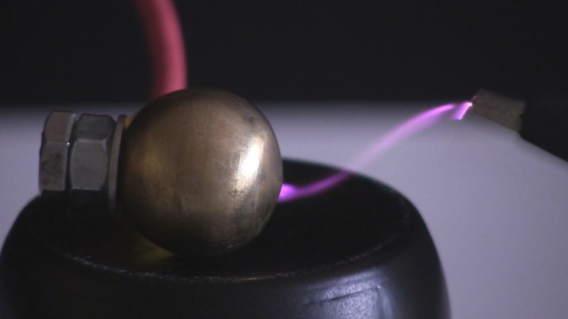
Having hacked away with high voltage for many years I’ve ended up using a large number of very different high voltage sources. I say sources and not power supplies because I’ve even powered a corona motor by rubbing a PVC pipe with a cotton cloth, making use of the triboelectric effect. But while the voltage from that is high, the current is too low for producing the necessary ion wind to make a lifter fly up off a tabletop. For that I use a flyback transformer and Cockcroft-Walton voltage multiplier power supply that’s plugged into a wall socket.
So yes, I have an unorthodox skillset when it comes to sourcing high voltage. It’s time I sat down and listed most of the power sources I’ve used over the years, including a bit about how they work, what their output is like and what they can be used for, as well as some idea of cost or ease of making. The order is from least powerful to most powerful so keep reading for the ones that really bite.
Triboelectric Effect
You’ve no doubt encountered this effect. It’s how your body is charged when you rub your feet on carpet and then get a shock from touching a door knob. When you rub two specific materials together there’s a transfer of electrons from one to the other. Not just any two materials will work. To find out which materials are good to use, have a look at a triboelectric series table.
Materials that are on the positive end of the table will become positively charged when rubbed against materials on the negative end of the table. Those materials will become negatively charged. The further apart they are in the table, the stronger the charging.
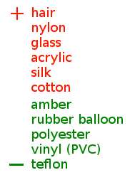
An example of where I’ve used this is to power the corona motor shown here. I vigorously rub a PVC pipe with a cotton cloth, and as the pipe emerges from the cloth, a sharp wire a few millimeters away takes the charge from the pipe. You can see this corona motor being powered by other power sources in the video here.
This would be considered an electrostatic power source because charge is accumulated on surfaces. Being insulating materials, that charge can’t move around.
The amount of charge transferred between the materials per unit of time is small meaning that the current available is small. You won’t be powering any heavy loads with this, but the corona motor powered this way turns at around one revolution every 5 seconds and can be stopped with the light touch of a finger. You already have a feel for the power from getting mild shocks from touching doorknobs. This is of course an easy power source to make.
Wimshurst Machine
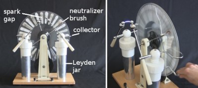
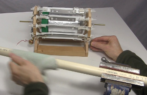
A Wimshurst machine is also a high voltage/low current power source. It consists of two counter-rotating disks, usually rotated with a hand crank. The disks have metal sectors on them that are spaced apart. The charging occurs where the neutralizer brushes contact the sectors as they pass by. That charge is then removed at collectors on the left and right edges of the disks and is usually accumulated in Leyden jars (capacitors) and across a spark gap where a spark occurs when the voltage is sufficient to break down the air in the gap.
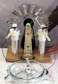
But if you’re making use of the Wimshurst machine then you’re usually not producing sparks. In the photo you see wires going from the Wimshurst machine to a ball cyclotron, making the balls in it rotate around inside the bowl.
The voltage with this one is limited by your losses in the Leyden jars and spark gap and your load. That’s why efforts are made to have everything be well rounded. The spark gap also limits the voltage and with this one I’ve produced sparks around 3 inches/7 centimeters long.
The current is indirectly determined by the disks’ diameter. That’s because larger selectors will produce more charge than smaller sectors. Also, the faster the disk turns, the more sectors will pass by the collectors per second and so more charge will be available.
A Wimshurst machine can’t provide enough current to make a lifter fly. However, it does provide enough current to power a smoke precipitator.
They aren’t too hard to make. I find that the trickiest parts are to find or make the pulleys needed for transferring the hand crank rotation to the disks. The disks can be acrylic which you can cut with a scroll saw or laser cutter, and often small Wimshurst machines are made using CDs.
Van de Graaff Generator
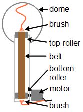
From the outside, a Van de Graaff generator looks like a big ball, or dome, on top of a vertical tube and more stuff at the base of the tube. While that dome is hollow, inside the tube is a belt on rollers. The stuff at the base of the tube includes a motor to turn the rollers and belt. The outer surface of the belt is charged by a combination of the same triboelectric effect we spoke of above, and some nearby sharp pointed brushes. That charge is transferred to the outer surface of the dome.
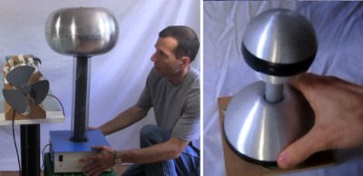
The amount of charge that can accumulate on the dome is limited only by its diameter. A smaller diameter dome can be thought of as a sharper object than a larger diameter dome. Sharper objects have stronger electric fields surrounding them, which break down the air more easily, taking charge from the object. The big Van de Graaff pictured is rated at around 400kV and the small one is around 80kV.
They’re still a low current source, as the current is produced by the triboelectric effect at the belt and rollers and mechanically transported by the movement of the belt. Wider belt and rollers and a faster rotation gives higher current.
They’re medium hard to make. Since the triboelectric effect is involved, the rollers and belt have to be the right combination of materials. For a small one the dome is often a soda can and for a large one it’s often made using metal salad bowls or a large garden ball.
Flyback Transformer
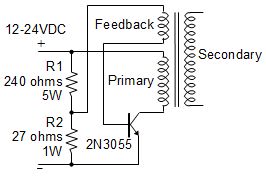
Moving on to the higher current power sources, an often used type is a circuit using a flyback transformer and one or more transistors. As expected, the flyback transformer has a primary winding which induces a current in the secondary winding. However, there’s also a feedback winding which at the same time shuts down the transistor which stops the current going to the primary. This causes the magnetic field to collapse and a large high voltage spike to appear at the secondary. Since there’s now no more current on the feedback coil, the transistor turns on again and the cycle repeats.
A similar circuit using MOSFETs exists called the ZVS flyback driver but as I haven’t made one I’ll refer you to this one put to use making smores.


Flyback transformers can be bought online but can also be salvaged from old CRT TVs and CRT PC monitors. They’ll most often have high voltage diodes built-in after the output of the secondary winding, which means the output is DC.
I built mine into the small cube shown above. You can see the nice continuous arcs you can get from it. I’ve also powered a Jacob’s ladder. Mine produced around 20kV output with a high current.
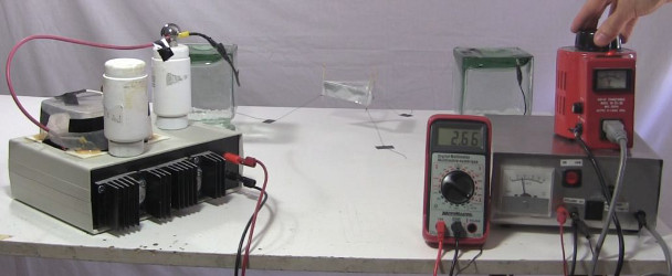
Flyback transformer plus Cockcroft-Walton voltage multiplier
If you’re lucky enough to find a flyback transformer with no built in diodes like the one shown here, then at the output you can add a Cockcroft-Walton voltage multiplier circuit. This multiplier consists of capacitors and diodes that take the flyback’s alternating output and smooth it out to flat DC but while multiplying the voltage over some number of stages. The number of stages simply depends on the number of sets of capacitors and diodes you add on. Each added stage increases the output voltage.


The voltage will have been stepped up, but the current will be lower than without the multiplier. It will still be high though, high enough to provide sufficient ionization to make a lifter fly.
You can make your own multiplier boards or you can buy multipliers. The ones you can buy are usually called triplers since they have three stages. They’ll raise a 20kV input to 30kV, also sufficient for flying a lifter.
An almost out-of-the-box source of these types of power supplies is to use an old CRT PC monitor. Simply remove the high voltage wire going into the cathode ray tube and use that wire. I do find that long sparks will damage these monitors easily so be sure to include around 240 kilohms of at least 2 watt rated resistance in series with the output.
These are the interesting high voltage sources with which I have experience. But I’d love to hear about your own high voltage hacks in the comments below. I’d also enjoy hearing questions or ideas on using or building high voltage supplies so don’t be shy.


I’d make sure that 240 kilohms of at least 2 watt resistor is long enough stand off HV between its leads while I was at it.
Oh and lets not forget props to Misters Tesla and Marx while we’re at it :)
Haha. Edison was such a dick.
Headline should have been “A corona-copia of high voltage sources”
LOL! Brilliant. Wish I’d thought of it.
I miss the glorious NST as well as the mighty MOT in this read…
Oil burner transformer and pole pig too.
Don’t forget the epic RTG HV transformers. The one described in the link below outputs 100kV:
http://c4r0.elektroda.eu/_hv/index.php?page=xrays/budowa&lang=0
I have a NST tucked away. Someday I’ll make a power supply out of it. I’ve used MOTs for a few things, but never high voltage. They have scary current to go with that HV, but there are some fun things you can do with them.
Agreed! A mains connected unmodified MOT is far too dangerous. I always re-wind the secondary to something sensible.
There are also the piezo electric spark ignitors in grills and gas lighters with triggers. Those can produce some high voltages as well and they’re compact so they can be practical for some applications. I’m also curious about how much high voltage one can get from a regular store bought battery while maintaining some current – I noticed some of the badge hacks on here last year and they peaked my interest.
http://hackaday.com/2015/12/09/the-best-badges-of-the-supercon/
http://hackaday.com/2012/05/22/automatic-capacitor-charger-lets-you-have-fun-with-sparks/
http://hackaday.com/2016/01/26/its-a-bird-its-a-plane-no-its-high-voltage-eprom-man/
Neon Sign Transformers are by far the simplest and most forgiving of the HV experimenters options for sources. If you know someone at a sign supply place, you can gain access to a large supply of surplus transformers, some of which may be very useful for experimentation. A lot of times they will just give them too you, as they have to pay to dispose of them. That being said, older NST’s may have toxic chemicals inside them used for the potting compounds, so don’t just throw them away when you are done, and unless you are prepared for a real challenge and making a huge mess, don’t try taking them apart! Its also important to find ones without built in breakers or protection circuits, or you will not have much luck doing anything with them.
Like you said, most new ones have protection circuitry. I put a power strip on mine; have to power cycle it every time it is shorted out or losses an arc. That said, much safer for simple experiments but adding a capacitor or making long arcs is nearly impossible.
We used ignition coils from cars.
2nd this, vehicle ignition coils are comparable to those vintage, rectifierless TV flybacks, but MUCH easier to source. Those designed for small vehicles (e.g. mopeds) can be quite compact and still pack a punch on 12V.
You had a perfect setup for a “coronacopia” pun and you missed it.
Wait no twelve foot Tesla coil? (:
I have a one foot Tesla coil… but I’m still improving it. I get streamers from the topload only if I put a needle on it. I work on it every now and then in hopes of not needing the needle.
Don’t forget the Kelvin water dropper! :D
I’ve wondered how big one could be made!
I haven’t done an exhaustive search but the biggest one I’ve seen is this one by Derek of YouTube channel Veritasium. https://www.youtube.com/watch?v=rv4MjaF_wow
That’s a cool video!
I…I…I did a bad thing, and read the comments. I don’t know how dumb people stumble onto electrostatic device videos and think they could charge a battery. Or that the device works because “water molecules are little magnets and they went through a coil”. There was a heated debate about distilled water versus tap water going on that was awsome though.
I’ve never made a Kelvin water dropper but will try a simple setup soon. This really was a good article!
Have fun zapping stuff for science, man! :)
Laser printers have delivered a variety of HV Supplies over the years, damn even modern florescent bulbs are good for 3000V in a pinch
Anyone have any thoughts on a HV – meter to actually measure the voltage these circuits and devices are producing? Years ago in a High school electronics program we used a HV volt meter that was a long plastic / ceramic device with a handle containing a meter and a ground or negative lead (rather long heavy gauge wire with an alligator clip) the other end was a metal probe tip about 1/4″ long, the whole device was 2 or 3 feet in length. I remember it being used on 2nd anodes of tv sets and a couple other HV power supplies, I do not recall a brand or much else about it. A meter to read the output of these supplies and devices would need to be very low impedance as to not pull down the voltage by acting as a large load and pulling excessive current. Safety also demands careful thought, longer and more insulation are good things, hand held would not be my first choice! can any body provide a design / schematic for such a meter? any other thoughts on how to get actual voltage measurements from Van de Graaff generators and other devices please!
You can make a cheap one with Neon Tubes and resistors. Or just accurately spaced spark gaps.
http://rimstar.org/equip/hv150kvprobe/hv150kvprobe.htm
Or buy one at a farm and garden store. They usually sell electric fences and the ‘shocker’, as well as an insulated wand with multiple Neon tubes to help troubleshoot fence problems. If they don’t sell them they definitely know who does, I guarantee it. Your local farmer/farmstand may know as well.
.
I can’t vouch for the accuracy though. There is data abound online for determining voltage of an arc based on electrode type, style, humidity of the air and, most importantly, length of the arc.
https://en.wikipedia.org/wiki/Paschen%27s_law
http://www.kronjaeger.com/hv/hv/msr/spk/
Good luck! (I may or may not like to play with dangerous arcs.)
For the version with a meter, antique shop. Look at all of their electrical stuff, don’t just ask if they have it. They might not know what you are talking about.
For a Van de Graaff generator sounds like you shouldn’t use a coil-based meter though.
Good luck!
Besides my homemade one that notarealemail gave a link to, for “lower” voltages up to 40kV I’ve used the Fluke 80K-40 HV probe a lot. http://en-us.fluke.com/products/all-accessories/fluke-80k-40.html. I rarely use it handheld since it’s easy enough to fix it in place as part of the experimental setup, but I have done handheld a few time. It’s quite safe. Of course other aspects of the experiment are usually dangerous and precautions have to be taken there.
Two foil meter. They spread apart proportional to the voltage. Calibrating it could be a problem, though.
I found another one, though I hope nobody uses these anymore!
https://en.wikipedia.org/wiki/Induction_coil#Mercury_and_electrolytic_interrupters
High voltage source for spark-gap radio transmission and x-ray generators!
https://upload.wikimedia.org/wikipedia/commons/7/79/Mercury_turbine_interrupter.png
How did they ever come up with their techniques? From that page: “When the primary current passed through it, hydrogen gas bubbles formed on the needle which repeatedly broke the circuit. This resulted in a primary current broken randomly at rates up to 2000 breaks per second.” They certainly had a different toolbox back then! Fascinating.
I know! It seems like they just threw everything at a high voltage source and recorded the results. I was really surprised when I came across this. They did a lot with Mercury back then, but it usually was inside of a tube.
I’d rather be shocked by a CRT than be anywhere near that thing!
I got lucky and found a Fluke 80K-40 high voltage probe at a thrift store, paid I think $3 for it.
You can make your own blade electroscope for higher voltages. Built carefully, it provides essentially no load on the power source and can be built to the sensitivity of your choice. Don’t bother with a foil electroscope, they aren’t really repeatably calibrateable.
Even Amazon has some blade electroscopes around $20 to $30.
$3 for an 80K-40! Sweet.
Electroscopes are awesome. I’ve used mine countless times for relative measurements and checking polarity.
Have you been able to assign voltages to the different blade angles, or do you use it for relative measurements only? At first thought I would think that the losses would be too great, but as you said, build it carefully.
I have not tried calibrating mine yet. I’m building a training aid, a small suitcase (used to be a camcorder case) with low and high voltage sources, a Crookes tube, and blade electroscope. I’m going to make some regulated high voltage supplies and use those to calibrate the electroscope.
I have one electroscope that I bought through Amazon, but I’ll build the one that is going into this case. I need to use bearings as frictionless as possible. Maybe just knife-edge, as it only has to rotate 90 degrees max. Stiction is an issue, so oiled ball bearings are out.
Can I use output from flyback with diode to cockcroft walton ckt to multiply them more?
I’m not sure. Hopefully someone else knows for sure because I’d like to know the answer too. I take it that you have a flyback with builtin diode instead of one with no diode and you’re wondering if that can be used to power a Cockcroft Walton voltage multiplier. I’ve always used one with no builtin diode. According to https://en.wikipedia.org/wiki/Cockcroft%E2%80%93Walton_generator a multiplier takes pulsed DC as well as AC and I think the raw output of a flyback with a single builtin diode is pulsed DC. I’ve observed it on a scope as flat DC but I think I had some capacitance in my measuring method that smoothed it out. Anyone?
I suspect that with only the 10M input impedance of the scope probe, the parasitic capacitance of the wires and at the input of the probe is simply charging up like any power supply. Put a 1M or lower resistance from anode wire to ground, and you should see the pulsed DC. Steve Greenfield AE7HD http://www.linkedin.com/in/stevenjgreenfield
Hello sir,
Can I use “rectified” flyback transformer (new type), instead of AC flyback transformers (old type), for input power of this “capacitor and diode” combination circuit. Would this circuit work by input of “rectified flyback transformer”.
No, the Cockcroft-Walton voltage multiplier circuit (the capacitor and diode combination circuit) needs AC as input whereas the flybacks with built-in diode (rectified) puts out pulsed DC. Sadly, flybacks without the diode are hard to find and so are ones where the diode can be easily removed.